Work Plan Area
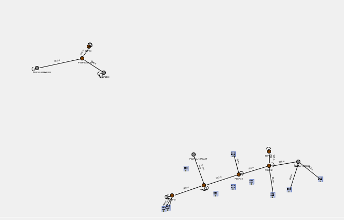
General Work Plan View Features
Once your Design contains structures, anchors and attachments, there are several functions available via right-clicking your mouse that can prove useful.
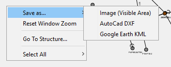
The first set of options is about saving the Design in a few different ways:
- Save an image of the visible area of the screen.
- Save the entire Design in AutoCad DXF format with enough detail to reproduce a drawing of the entire Work Plan Area.
- Save the structure locations for the entire Design in Google Earth KML format. This format is useful for use in mapping and other GIS systems.
The Reset Window Zoom feature will reset the Work Plan Area's zoom amount to the same amount as when the project is first opened.
The Go To Structure... feature is the same as the similarly named feature under the Edit menu of the main application and the Find button in the PLan View Toolbar.
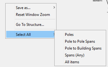
The Select All feature allows you to select all the Poles, Pole to Pole spans, Pole to Building spans, all Spans or everything within the Work Plan. This can be used afterwards along with other right-click menu items as an easy way of applying changes to many items at once.
Making Span Connections
Making a logical connection between two poles is a necessary step before attachments can be added. To do this, select one pole and while holding the Control Key down on your keyboard, hold the left mouse button down and drag it to the desired pole. You will see an arrow appear attached to the first pole. When it is on the other pole, let go and your connection should still be there. You can now add attachments via the Span functions below, or by right-clicking on the span.
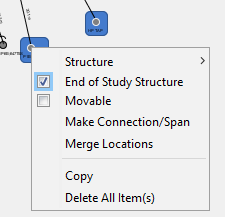
As an alternative method, you can select any two items (poles or buildings) and right-click on one of them. One of the options provide will be "Make Connection".
Adding to Your Project
In addition to Importing Data and using the features in the Coordinates Editor, there are two additional ways of adding content to your project:
- Drag and Drop from the Work Plan Palette (see Plan View Toolbar)
- The Pole Sequence Loading feature
Drag and Drop
Any item in the Work Plan Palette (upper right-hand window) can be dragged onto the Work Plan Area. This will create items according to your defaults being added to your project at the location where it is dropped.
Visualization and Connections
Creating Span Connections
Once poles are located on the scene, you will first need to create a connection between two poles (or a pole and a building or long-span anchor) before you can add span attachments to them such as power conductors or messengers.
You do this by first selecting a pole. Then while holding down the CRTL key and the left mouse button, drag the mouse to the item you wish to connect. You will see a line and arrow appear at the end of where the mouse is pointing. When the arrow is touching the object you wish to connect, simply release the mouse button and CTRL key. Now you have established a connection.
You can now add attachments to this connection. Please note, if you haven’t added attachments to this connection before exiting Quick Pole and saving your project, you will need to create this connection again as it will not be permanently saved unless it has at least one attachment.
Visualization Rules:
On any connection that goes pole to pole, pole to building or Mid Span Tap to Building will be visible, regardless of attachment types or distance.
Guy wires that go from a pole to anchor(s) will not be shown in most cases, to reduce visual clutter in the Work Plan Area.
Connection Rules:
When making a connection from a pole or Mid Span Tap, the only possible solutions are to other poles or buildings.
Context sensitive menus will contain only the choices that are appropriate based on what is selected and what item you right-click on to bring up the menu.
Other Functions:
- Pole Sequence Loading
- Span Attachment Functions
- Single Selected Structure Functions
- Multiple Selected Structure Functions