Pole Sequence Loading
As the name implies, you enter new poles by defining the sequence of the poles. You define a starting point, a direction and distance for each pole structure you would like to add. To do this you need to perform a two step process.
To start this process, first select the starting pole to create a string of poles from. This could be the start of a pole line or lead off a pole line. You will need to have three connected structures placed in the desired direction for the next step to work.

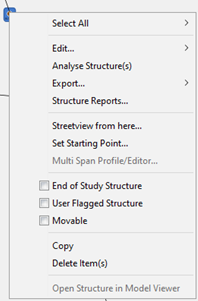
Right-click on the starting pole and select the "Set Starting Point..." menu item. This tells Quick Pole that this is the starting pole of your sequence of poles. When you do this, a message appears at the bottom of the screen indicating that you have a starting point defined.
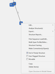
The next step to start the process is to select two more connected poles in the direction you wish to extend the pole line. You can now hold the left mouse button down and drag across the Work Plan to cover the desired poles (second and third poles). You can alternatively add individual poles to the current selection by holding down the Control Key and left-clicking on more poles. After selecting these poles, do a right-click on either of the selected poles to bring up the "Pole Sequence Load/Edit" menu choice.

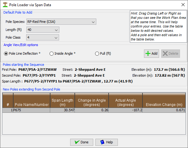
This will cause the following Dialog to appear:

The middle section of the Dialog shows the first two poles that define the starting point and initial direction for the sequence. The third selected pole is included in the table to provide an example of how this sequencing will work.
New poles via the "Add" button will be added to the table based on the pole defaults show at the top of this Dialog. You can change these settings at any time while creating the desired sequence. The basic operation of this Dialog is to add new poles to the sequence and edit specifics in the Table. At the end of editing each field for each pole, the Work Plan is automatically updated. You may want to drag this Dialog to the side so that you can see the Work Plan Area and validate that it is doing what you intended as you enter data.
Fields:
- Pole Name/Number - This is the designation you will see everywhere related to this pole.
- Span Length (m) - Enter the distance from the previous pole to this one.
- Change in Angle (degrees) - This field will change based on the "Angle View/Edit" option chosen. Pole Line Deflection is also commonly called "Line Angle". Inside Angle is often provided by CAD systems. Pull is a another method that can be used. If the pole line is straight (tangent) to this pole from the previous pole, leave this field blank or enter a zero. If this pole is a corner pole, enter the amount of the angle in degrees that this pole deviates from a perfectly straight line based on the last two poles. Positive values will deflect the pole in a clockwise direction, while negative values will represent a counter-clockwise direction. Watch the work Plan Area as you enter each pole to confirm the result is what you intended.
- Actual Angle (degrees) - This is informational to show you the resultant angle of the individual span.
- Elevation Change (m) - Enter how high the base of this pole is above the previous pole. If the pole is lower than the previous, enter a negative number.
In addition to entering new sequences of poles, this same Dialog can be used to edit existing pole sequences. To do this, after you select your starting pole, select the whole range of poles that you would like to edit. You should know that the specific poles you select for the sequence must not include lateral/branch or other poles that are not part of a continuous line. Some checks and messages are generated if you selected an inappropriate pole. This feature can be used over and over again on the same or different pole line sections in your project. To assist with the later movement of poles, all connected anchors and buildings to the poles moved will be automatically adjusted by the same amounts. This retains the initially set span/lead lengths and angles.