Nonlinear Structural Analysis
Load Nonlinearity
If the assumed loads that are applied to the structure in the analysis can change due to movement or deflection of the structure, this can be an important secondary effect. The loads are said to be Nonlinear as they are neither constant nor predictable separately from the structure. When Load Nonlinearity is considered during Structural Analysis, the loads applied to the structure are normally adjusted iteratively throughout the Nonlinear Analysis.
These effects are very applicable to Transmission and Distribution Lines, but primarily to Distribution Lines as their span lengths are shorter. Over a shorter span, the deflection of the structure(s) will have more of an impact than over a longer span. The primary application that creates Load Nonlinearity for Line Structures is from the various wires under tension that may be attached between structures. The tension forces that are applied to the structures will change in both magnitude and direction as their supporting structures deflect. Since the structures deflect in response to all applied loads, determining the final structure deflection and internal loads is therefore an iterative process.
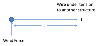
The following example will demonstrate. A structure with the tension T of one wire attached to another structure a distance of approximately L away is under study. The structure is subjected to wind load on itself and the apportioned wind load from the wire.
Starting Condition
 In this initial condition it is assumed that the structure has no deflection when the forces are initially applied:
- Fx = T
- Fy = Wind
- Wire Length = L , based on the span length between the structures and the installation tension.
Initial Response

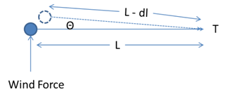
The structure deflects in response to the loads that were applied. It moves away from the wind that was applied and pulled slightly towards the tension in the wire. The wire length is now shorter than it was before, as the structure has now deflected towards the wire exerting the tension. This reduces the tension T to T – dt. The direction of T has changed slightly as well with the introduction of a small angle Θ to the horizontal.
Secondary Response
The loads have now changed as the angle and magnitude of the Tension T are now different.
- Fx = (T – dt)* Cos Θ
- Fy = Wind – (T – dt) * SinΘ
- Wire Length = L - dl
The effect of the angle Θ on T producing some Y direction forces will tend to help support the structure against the wind forces. The structure will no longer need to support the entire Wind load, so it does not need to deflect as much as it did initially. The reduction in tension of the wire will reduce the amount of pole deflection in that direction, as well.
Additional Responses
The adjustments to the net forces acting on the structure will result in less deflections overall.
 This process of force adjustments is iterative until the structure's deflections stabilize.
These Load Nonlinearity effects are most often used in the following scenarios to more accurately estimate the structure and attachment responses in the following scenarios:
- Uneven span lengths on a tangent pole line.
- More wires coming to the pole than are going towards the next.
- Anchor/guy combinations that are not in the ideal location/angle.
Load Geometric Nonlinearity
Very advanced Pole Line Design Software, such as Quick Pole, can separate inline tension changes due to deflection from general Load Nonlinearity that also considers tension angle changes. This is important in tangent lines where all structures deflect in the same direction due to wind, at the same time. Therefore, each structure can only experience inline deflection/tension changes. To consider tension angle changes as well would be inaccurate and possibly unsafe.
Load Geometric Nonlinearity is considered to include angle effects plus inline deflection/tension effects, whereas Load Nonlinearity only includes inline deflection/tension effects.


