Quick Pole Verification
Introduction to Unguyed Structure Response
The focus of this category of tests is to confirm that the basic pole model behaves as expected to create the correct deflections and stresses from known input loads. Testing both deflections and stresses are critical in evaluating if Pole Loading Results "reasonably represent how a real pole behaves". In addition, the amount of stress created for a specific amount of deflection is a key indicator that the "Stiffness" of the pole segments are accurate. The relative stiffness of the pole segments in relation to the location of the applied loads and the stiffness and location of guying, are the major items that determine the pole's behavior along its length (stresses & deflection).
It is assumed that all software tools utilize Finite Element Analysis. That means that the pole is assumed to be modeled into many different pole segments and assembled together to represent the whole pole. The tests listed here will validate that these assembled pole segments do in fact come together and are modeled accurately enough to provide reasonably accurate results. This model is tested across the longest distance possible of the pole in order to ensure any model inaccuracies are exposed that may not appear on shorter distance tests.
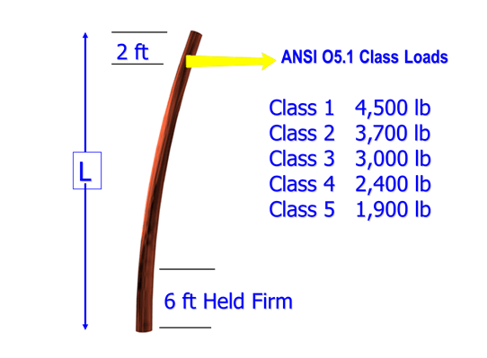
 Most of these tests were modeled after the Pole Class Definitions in the ANSI O5.1 standard. The amount and location of the applied load matches exactly with how the pole classes were defined to create its dimensions. This means that the fibre stress utilization should be very close to 100%, recognizing that the pole dimensions for the groundline were rounded to the nearest 1/2 inch.
In some cases the CSA 015 standard suggests lower maximum fibre strength ratings and slightly different dimensions for the same pole. For this reason one of these tests will be dedicated to a CSA standard-based pole to ensure that the software can properly address Canadian as well as US poles.


