Quick Pole Verification
Load Nonlinearity Verification Results
The loads that can change in response to the movement of the pole are the attachments that span to other poles. Wire attachments will have a starting maximum tension that would be applied to the poles. If the poles move towards each other, this lessens the tension. Conversely, poles that try to move apart result in an increase in wire tensions. The wires will behave this way regardless of what situation is causing the effect. In practice, two main situations arise:
- Balancing of un-equal inline tensions. Some software tools use an average span length for both sides of the pole before calculating their tensions. Quick Pole calculates tensions based on actual span lengths and then shows the end result of the pole deflecting/stressing and the wire tensions changing.
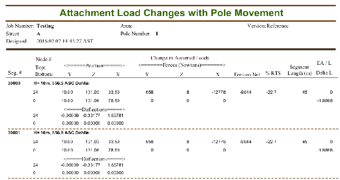
- Support of wind load applied to a pole by wire attachments going to poles in lateral directions. This is a minor impact and is more of a Geometric Nonlinearity related to the attachment loads. Since the span lengths are long compared to the pole's deflection, the angles created are small and therefore the impacts are small. These results can be seen in the Attachment Load Changes report.

Download a project file showing an extreme example of this effect. It has five 556.5 ASC Dahlia conductors attached in one direction from an unsupported 40 ft Class 4 WRC cedar pole. Under CSA Heavy Loading, the maximum tension applied to the pole by each of the wires is 10990 Newtons, or 25% RTS. Under this load from all five wires, the pole's tip deflects about 1.89 meters, which in turn reduces the tension in these wires to about 3% RTS. Again, this is an extreme example that is not typical; but sufficient to demonstrate the ability of Quick Pole to re-calculate wire tensions during the analysis procedure as the pole deflects.


