Design Window
It is assumed at this point that you have either created a brand new Quick Pole project file via File->New or you have just loaded an existing one via File->Open.
Suggested Process
To start a Design in Quick Pole, the suggested steps to follow are as follows:
- Define Structure locations on the Work Plan
- Connect the Structure together to define Spans
- Update the poles to the correct length, species, class and set the Depth of Setting or Height Above Ground.
- Place attachments on one Span at the appropriate heights. Copy span attachments to similar poles and adjusts heights/attachments as necessary. Repeat for each pole lead that has different attachments.
- Clone a copy of the Design with all field data up to date. Add attachments or make other changes to the cloned copy.
- Confirm Project Settings and other details
- Analyze Results
- Edit, suggest Make Ready changes, Analyze Results, repeat until satisfied.
- Document Design, print reports, etc.
The remaining sections of this chapter explain in detail how each area/feature supports this process.
Design Window
For each Design a separate Window is required. It is comprised of two separate main tabs:
Settings – This is where you enter information specific to the Design, select defaults you want to use for new items added to the project and to select or over-ride environmental loadings (storm, ice, wind, temperature,…)
View – This tab contains both a Plan View tab, an Analysis tab and a Make Ready Manager tab.
- The Plan View is an aerial view of all pole structures and the connectivity between them. Most of your Project work will be done in this tab.
- The Analysis tab is the place where you would initiate analysis of the entire project, see instant results and generate summary and detailed reports. This is covered in the next sections.
- The Make Ready Manager tab is where you compare the current Design to the original (before cloning) to ensure that your Make Ready notes are in line with the changes detected between the designs.
Settings
The Settings tab of a Design Window enables you to set certain variables that impact the entire Design. Many act as a default setting that can be overridden on an item by item basis in the Plan View.
Regardless of how the Design was initially created or what defaults were applied, all Design Settings can be altered here.
The Settings Tab can be thought of as being grouped into different sections, which will be covered separately:
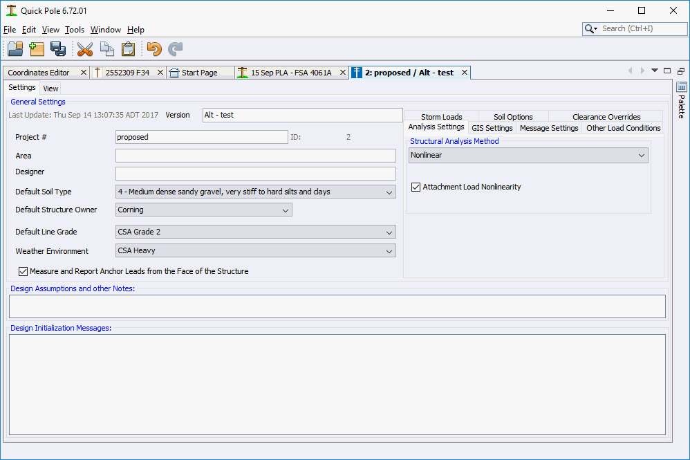
General Settings:
Version:
Use this field to distinguish this Design from all others in the Project File.
Project Number:
This entry can be edited, but normally matches the filename of the Project File.
Area:
This is an additional field that assists in identifying the area that this project is in. You can enter anything such as city, substation identifier, feeder identifier, switching center, wire center, ...
Designer:
Usually enter the name or ID of the person responsible for the Design of this project.
Default Soil Type:
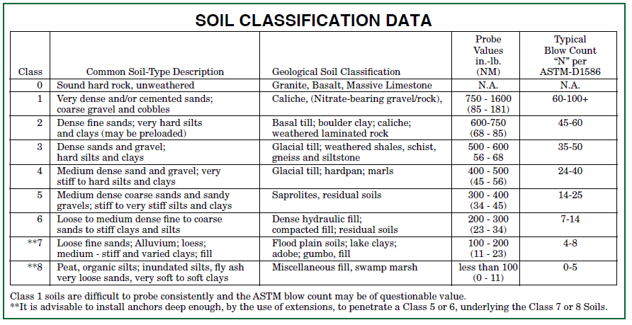
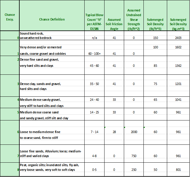
The stability of poles and the holding strength of anchors are dependent on the Class of Soil, as defined in the Universal Soil Classification System and adapted by A.B. Chance Encyclopedia of Anchoring. When creating a new Design, this value is preset based on user default preferences. You should adjust this value to represent the most appropriate default Soil Class for the area the Design covers. This way new poles and anchors added to the Design will already have this value set. You can also change the soil Class for each item in a Design individually. This Default Soil Class setting can often help you save time editing your Design.
Default Structure Owner:
Various selection choices can start based on a good choice for the Organization or Company. Most often this value is used to help set or reset the framing of wires on the pole. Only values that have been defined in the DataManager are available here. So you may or may not want to enter new values in the DataManager before starting a new Design.
Default Line Grade:
It is most efficient to set the most common Line Grade here for all items added to a project. Initially the value that is set in User Preferences is shown here as the default. You can always adjust specific items that require a different Line Grade individually later. All CSA and NESC Line Grades are available.
Weather Environment:
This setting defines the overall Storm Loadings required for the entire project. All CSA and NESC defined combinations of wind, ice and temperature are available for selection.
Anchor Leads form the Face of the Pole:
This is a preference setting that is specific to this specific project. Different geographic areas, and hence different projects, could have different requirements. This setting impacts the anchor lead lengths shown on reports and also the value presented for editing. The alternative to the measurements being from the front of the pole is from the exact center of the pole. Both methods have their merits. This setting has no impact on how anchor locations may be imported from data files using GIS coordinates.
Analysis and Other Settings
There are several tabs in this section that cover different settings available.
- Analysis Settings
- GIS Settings
- Message Settings
- Extra Load Conditions
- Storm Loads
- Soil Options
- Communication Clearance Settings
Analysis Settings
The Nonlinear Structural Analysis Method is the default for Quick Pole to use. However, it is also possible to do just a Linear Analysis by setting this choice on the Design Setting tab. This value will be saved with the Design and will be used the next time this Design is opened for analysis.
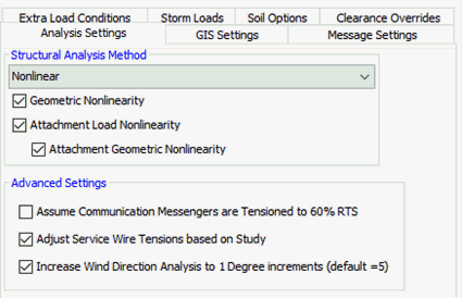
The above image is what you would see if you have "Expert Options" turned on via Tools->Options->Expert Settings. Below is the default view that most users would see. The options that are hidden are not necessary in the majority of situations, but are available if you need them.
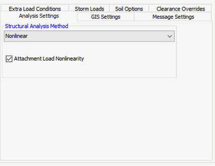
Specific to the Nonlinear Analysis method are two additional options which are normally on by default. They are considered Advanced User options and should only be changed if you are sure of what they do. They can have a huge impact on the results of a Structural Analysis.
- Geometric Nonlinearity- Additionally considers the movement of the Structure and its effects on guying and other structural members (stretching, angles, etc..). This is mandatory in CSA Standards.
- Attachment Load Nonlinearity - Additionally considers the movement of the Structure and its effects on the stretching/slackening of line attachments and the corresponding impact on the tensions/forces that they exert onto the pole.
- A sub-option is available that controls how one aspect of Attachment Non-linearity is applied. Without this option, tension changes of attachments are only changed for in-line changes in pole deflection. If this sub-option is enabled, tension changes due to lateral pole movement will also be considered, which is the default. This option is extremely similar to Geometric Nonlinearity as the direction of the attachment loads changes with Structure deflection, in addition to its magnitude.
Assume Communication Messengers are Tensioned to 60% RTS - While actual sags & tensions are calculated and provided in various reports, the actual load applied to the pole for the structure to support will be fixed at 60% of the Rated Tensile Strength of the messenger, if this option is set. A User may select this if they wish the pole line structures to be designed for the maximum amount of cables permitted under CSA and NESC rules. This setting is useful in cases where you want to ensure that additional cables can be lashed to the installed messenger without causing significant upgrades. The messenger tension is normally limited to 60% RTS and will be highlighted as an issue in Quick Pole if it goes beyond this value. While this setting does not place additional wind loading on the poles and wires, all corner and deadend poles and anchors will be designed for ultimate tension. Tangent poles are unlikely to be affected by this setting. Using this feature does not guarantee that clearances in the future will be adequate, only that the necessary strength will be present.
Adjust Service Wire tensions based on Study - There was a study of power service wire tensions completed by Bell Canada in Ontario in 2014. Through that study it was confirmed that most power service wires are not tensioned to the maximum amount allowed in the Power Utility's standards unless required to meet clearance requirements. In most cases for span less than 30 meters, the wires are placed to create 0.4 meters of vertical sag below the building attachment point; and that the average height of the power wire on the pole was 2.0 meters above the building's attachment point. If this option is selected, Power Service Wires and Communication Service Wires will be tensioned to create this desired sag profile. If the required tension to accomplish this is greater than the Power utility's standards, the standard value is used as the limit. Communication Service Wires are typically sagged the same way as that it is standard practice for communication wires to follow the sag profile of the Power wires in the same span to Buildings.
Increase Wind Direction Analysis to 1 Degree Increments - By selecting this option you will force Quick Pole to perform a Structural Analysis of each pole with the wind assumed to move around the pole in one degree increments (5 is the default). This option is not normally necessary, but remains for increased confidence that the 5 degree increment results are sufficiently accurate.
GIS Settings
GIS settings are optional as Quick Pole internally uses Easting / Northing (x,y) position values to calculate span lengths and angles. Quick Pole can work with or without GIS settings or coordinates. A few additional features are available (such as StreetView) if GIS settings are also utilized.
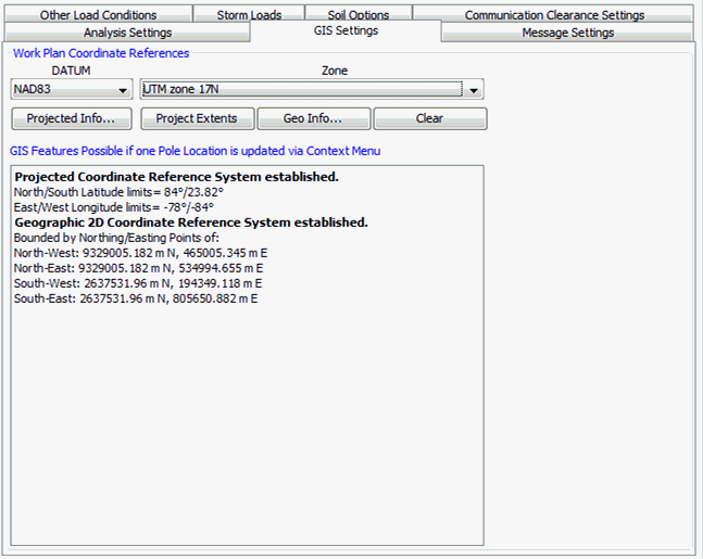
If you set the Datum and UTM Zone, GPS coordinates in degrees can be converted to exact Northing/Easting values for internal calculations. It also helps line up base layer maps with your project.
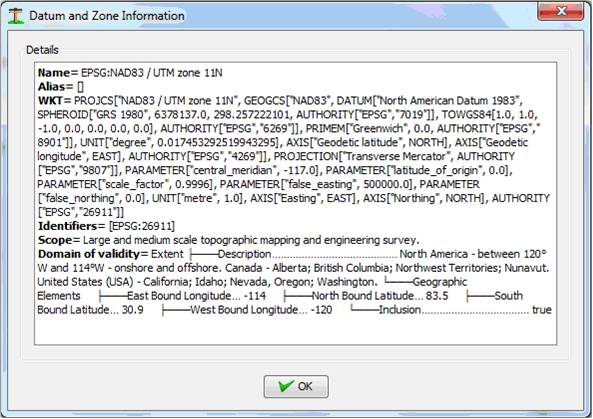
The Projected Info button can be used to get more detailed information on Datum selected to confirm you have made the best choice.
Message Settings
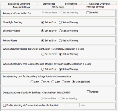
In this tab you can customize "how" and in some cases "if" Quick Pole will generate a message for certain conditions. This list of message options may grow in the future as it is driven by customer requirements. Some items cannot be ignored since they involve CSA/NESC code requirements. In that case you can only be adjusted to be interpreted as either an Error or just a Warning, but will always generate a message/indicators if violated.
- Primary->Comm Within 3m. A message can be generated if the top communications strand is within 3.0 meters of any identified primary voltage. For this feature to work, the lowest primary wires on the pole must have their voltage set to 750-22000 volts or greater. Primary Voltage Points can be added as an equipment item to facilitate detection of the lowest connection/device wire on the pole that is energized to primary voltages.
- Streetlight Bonding. If a Street Light is within 1.0 meters or below a Communications Messenger, it may not be properly grounded. Quick Pole cannot automatically recognize if a Streetlight is grounded, so it must generate a message if it falls within the separation criteria. In this case the generated message can be either an Error or a Warning.
- Secondary Risers. This item if for cases where Secondary Power Riser Cables/Conduit are not fully mechanically protected 1.0 meters or higher above the top communications strand.
- Primary Risers. This item if for cases where Primary Power Riser Cables are not fully mechanically protected 1.0 meters or higher above the top communications strand.
- When a Neutral violates the Line of Sight.... This option will adjust Line of Sight violations for neutral wires on spans less than 75 meters that have at least 0.3m of in-span vertical separation, to be Warnings as opposed to Error messages. Power Conductors that are Neutral Wires need to be identified as so for this to function properly.
- When a Secondary Wire violates the Line of Sight.... This option will adjust Line of Sight violations for secondary wires on spans of any length that have at least 0.3m of in-span vertical separation, to be Warnings as opposed to Error messages. Power Conductors that are Secondary Wires need to be identified as having voltage <=750 volts for this to function properly.
- Error/Warning Limit for Secondary Voltage Points... For items like triplex drip loops at the pole, many Designers allow closer separation requirements for items that come closer to the communication space at a certain location. Secondary Voltage Points can be located on the pole as a special equipment item at the lowest height measured in the field. This option will enable closeness of less than 1.0 meter to be flagged as a Warning as opposed to an Error.
- Detect Attachment loads for Buildings > Service Mast Limits (2649N). This item will evaluate the maximum tension of Power Service wires at building locations and detect any situation where it is greater than the amount permitted for Building Service Masts (600 lbs, 2649 Newtons); typical values for residential power service masts. Some caution should be used if Attachment Nonlinearity is enabled for poles with Power Services as they could be calculated to higher tension loads than the service wires may actually experience.
- Enable Warning at Communications Bundle Size Limit. Enable this option and set a value that you wish to be notified when a Communications Bundle Diameter exceeds this threshold.
Extra Load Conditions
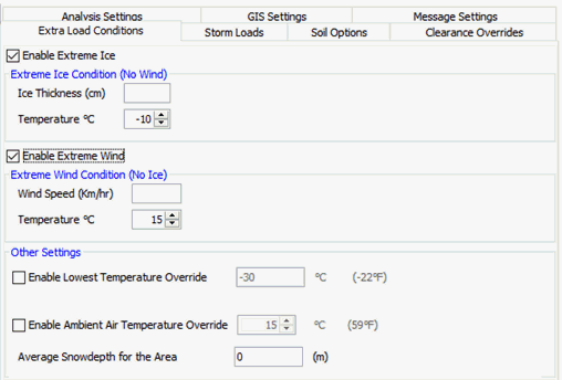
In this tab you can select and customize two additional storm conditions for Quick Pole to evaluate in your project. These additional load cases are applied to the Sags and Tensions of all wire attachments, plus all other loads on the pole structures, as appropriate.
Extreme Ice
The common use for this setting is to capture a severe icing event that would be reasonable to expect within the project’s area, or for greater certainty and confidence in the Analysis Results. Simply enter the thickness of ice that you require and the temperature that could exist before the ice accretion amount subsides. For instance, while it is most common for icing events to occur near the freezing point, in many areas the air temperature can drop in the following day or two with the ice still present. Items such as conductors and messengers will have greater tensions under both ice loading and under lower temperatures. For this reason, both ice and low temperature are entered. There is no significant wind expected in this situation. An additional Weather Load Case will be added to all Sags and Tension results, plus the structure and hardware attachments will see the worst of this condition and others set (such as Storm Values) for ice thickness.
The type of ice is assumed to be the same as that set for the entire project. So if the maximum ice event you want to model has a different ice type than your project, you will need to adjust the value entered into an equivalent quantity of the project defined ice.
Extreme Wind
The common use for this design condition is for Hurricane or severe wind storm events, for which ice is not involved. This design condition requires a Wind Speed and a specific temperature. An additional line item will be added to all Sags and Tension results, plus the pole structure and hardware attachments will see the worst of this condition and others set (such as Storm Values) for wind pressure.
Lowest Temperature
If you enable this option, you can change the default lowest air temperature that is used in evaluating Sags & Tensions.
Ambient Air Temperature
You can use this option to over-ride the average air temperature used to display results at average everyday temperatures.
Average Snow Depth
By entering a value here, this depth will be added to all Pedestrian category minimum clearance values.
Storm Loads
In most cases, choosing the proper Weather Environment setting will already define the exact Storm loading scenario that you require. There are cases where you believe (or have knowledge) that these storm values should be different in some way. NESC and CSA standards allow you to increase values beyond the minimums defined by the normal environment value. This area allows you to do this.
If the “Enable Storm Value Overrides” checkbox is checked, additional fields will become visible so that you can override specific aspects of the Weather Environment selected above. If this is unchecked, no override will be used in the calculations.
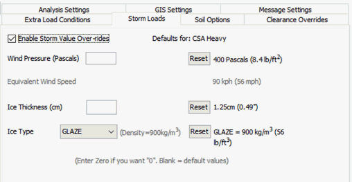
You can modify any one or all of the Storm Value settings with this option. The right-hand column of values shows what the current Weather Environmental Setting has for these Storm Values, in both Imperial and Metric units. Use the “Reset to Defaults” button to remove any override setting you may have for an item.
Wind Pressure:
The Wind Force per unit area (pressure) that will be applied to the pole and all attachments. This entry is expected as a number in Pascals (N/m2). For convenience, the equivalent Wind Speed is calculated in metric and imperial values in the line below. So, if you just know the Wind Speed you want, you can keep adjusting the Wind Pressure entry until it reaches the value you want for Wind Speed.
Ice Thickness:
Thickness of the ice accretion expected on the pole and attachments. Only centimeters is expected, so you may need to convert values in inches before entering.
Ice Type:
Most projects will never adjust this value from GLAZE or GLAZE-NESC. This represents solid ice. A few other types of frozen moisture are available for special applications such as Rime Ice and Wet Snow.
Soil Options

Quick Pole can evaluate the strength of the soil to support the poles being analyzed. It performs two tests which are optional and can be set to either an Error or a Warning.
- Ground Soil Strength Testing. This is the ability of the soil to resist the groundline moments that the pole requires to exert against it, based on the loads that are applied to the pole. If enabled, messages will be generated that compare the current Depth of Setting with that required according to "Brom's" method, based on the groundline moments and the strength of the soil.
- Vertical Bearing Capacity Soil Testing. This tests whether the soil is strong enough to resist the pole being pushed into the ground, based on the calculated vertical loads. This becomes important when a pole is more heavily guyed and/or the soil is weak. Calculations follow the methodology suggested by "Meyerhof".
For reference, here are the main soil parameters used in Quick Pole in these calculations:
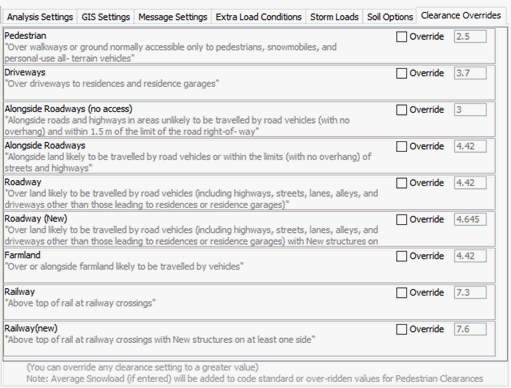
Clearance Overrides
Depending on which Standard base is chosen (CSA or NESC), various ground clearance settings for Communication Attachments are permitted to be overridden and increased. This is helpful where you want to ensure that you have more than the bare minimum clearances required by the applicable standard. These values can be raised above the minimum, but cannot be decreased. In the Analysis of a project, communication attachments will be evaluated for ground clearance against these values, if they are overridden. The individual items are self-explanatory and may be explained further in the applicable standard.
Design Notes and Initialization Messages
Design Assumptions and Other Notes
In this section you can type in any notes you want to record related to this Design. It has a limit of 10000 characters and will be printed in the Project Overview Report. You should note that each pole structure individually has two places where pole specific notes can be captured (Design Notes and Remedy/Make Ready Notes).
Design Instantiation Messages
When a Design is opened, it is automatically validated from a data perspective to ensure that all the items referenced in the Design can be found accurately on your computer. If there is any mismatch between them, Quick Pole brings these items to your attention immediately. In most cases items used in projects from Datasets will be copied into the project file so that all items will be found. In some cases you will need to re-match the item yourself, based on the data stored in your computer. In other cases Quick Pole will try to make an intelligent replacement suggestion for you. Quick Pole will identify which items are impacted so that you can locate them and ensure that they link to what you were expecting. Once you save your Design after the matches are complete, you shouldn't need to do this again.
View Tab
The View Tab is where most of the work specific to a Design is performed.
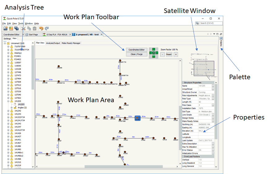
Analysis Tree
During Analysis of the Design, the Analysis Tree is populated and updated showing all poles, attachments and anchors used in the Design; sorted by Street and then by Pole Number. For more information go to the Analysis Tree section under the Interpreting Results chapter.
Plan View
The Plan View tab is where most of the Data Loading and Editing occurs.
These will be described in the following order:
- General Project Plan View Features
- Plan View Toolbar
- Coordinates Editor
- Adding items to your Project
- Selecting and Connecting Items
- Structure Functions
- Span Attachment Functions
- Clipboard Functions
- Structure Window
- Structure Pictures
- Structure Notes
General Project Plan View Features
Once your Work Plan contains poles, anchors and attachments, there are several functions available via right-clicking your mouse that can prove useful.
You can either Print the Work Plan Area or Save an Image of it by Right-Clicking anywhere in the Work Plan Area that is not on top of another object
.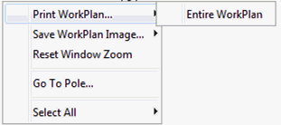
The Save WorkPlan Image feature allows you to select from:
- Visible Area - Just the area you are viewing at the time
- Entire Work Plan - The whole Work Plan Area, even if it doesn't all fit into the current viewing area.
- Selected Items - Select items one by one by holding down the CTRL key, or drag a rectangular box to select specific items you want to Save.
Using the Print feature will bring up a Dialog Box of available printers and the Save feature will bring up a Dialog to capture the file name and location of the file to be saved. The Save feature supports .JPG and .PNG file types.
The Reset Window Zoom feature will reset the Work Plan Area's zoom amount to the same amount as when the project is first opened.
The Go To Pole... feature is the same as the similarly named feature under the Edit menu of the main application.
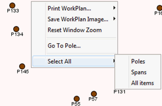
The Select All feature allows you to select all the Poles, all the Spans or everything within the Work Plan. This can be used afterwards along with other right-click menu items as an easy way of applying changes to many items at once.
Making Span Connections
Making a logical connection between two poles is a necessary step before attachments can be added. To do this, select one pole and while holding the Control Key down on your keyboard, hold the left mouse button down and drag it to the desired pole. You will see an arrow appear attached to the first pole. When it is on the other pole, let go and your connection should still be there. You can now add attachments via the Span functions below, or by right-clicking on the span.
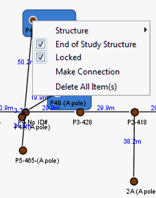
As an alternative method, you can select any two items (poles or buildings) and right-click on one of them. One of the options provide will be "Make Connection".
Work Plan Toolbar
This Toolbar contains some useful functions while in the Work Plan View..

Nudge Tool

After you select one or many items on the Work Plan Area, making sure its position is unlocked, you can use this set of four nudge buttons to move the item a minor amount in the direction shown on the button. Only items in an unlocked state will move. If some items are locked into position, no error will occur; they just won't move.
Zoom Tool.

Use this control to adjust the desired zoom level for the entire Work Plan Area. Higher zoom levels will make all items in the scene larger. The Satellite View will adjust itself accordingly so that you always know what part of the Work Plan Area you are viewing. For best results, first select the pole or poles you wish to keep in the view as the view changes magnification. Using the center mouse wheel also automatically adjusts the zoom level for you and will attempt to center the zoom action where the mouse is currently pointing.
Clean/Purge

Use this control when you wish to remove all items that don't have attachments to other poles. Buildings, Poles and Anchors that have no connection to other poles will be removed from the Design. This can be useful after certain edit actions, or data import activities and you have attachments already connected to the poles you are interested in retaining in the project.
Coordinates Editor
![]()
Pressing this button will open the Coordinates Editor Window and ensure it is populated with data from your Design. There you can add/edit the exact location of multiple items all at the same time. New Poles, Anchors and Buildings can be added at specific locations at the same time in this Window.
Adding to Your Project
In addition to Importing Data and using the Coordinates Editor feature, there are two additional ways of adding content to your project:
- Drag and Drop from the Work Plan Palette
- The Pole Sequence Loading feature
Drag and Drop

Any item in the Work Plan Palette (upper right-hand window) can be dragged onto the Work Plan Area. This will create items according to your defaults being added to your project at the location where it is dropped. If the Palette is not already open, simply hover the mouse over words "Palette" on the top right-hand side of the Plan View window and it will automatically expand for you.
Pole Sequence Loading
As the name implies, you enter new poles by defining the sequence of the poles. You define a starting point, a direction and distance for each pole structure you would like to add. To do this you need to perform a two step process.
To start this process, first select the starting pole to create a string of poles from. This could be the start of a pole line or lead off a pole line. You will already need to have three connected structures placed in the desired direction for the next step to work.
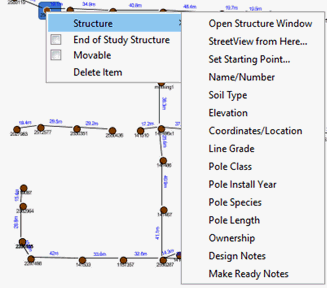
Right-click on the starting pole and select the "Set Starting Point..." menu item. This tells Quick Pole that this is the starting pole of your sequence of poles for further actions. When you do this, a message appears at the bottom of the screen indicating that you have a starting point defined.
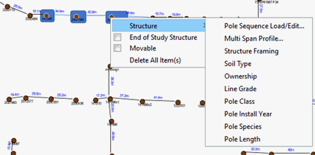
The next step to start the process is to select two more connected poles in the direction you wish to extend the pole line. You can now hold the left mouse button down and drag across the Work Plan to cover the desired poles (second and third poles). You can alternatively add individual poles to the current selection by holding down the Control Key and left-clicking on more poles. After selecting these poles, do a right-click on either of the selected poles to bring up the "Pole Sequence Load/Edit" menu choice.
This will cause the following Dialog to appear:
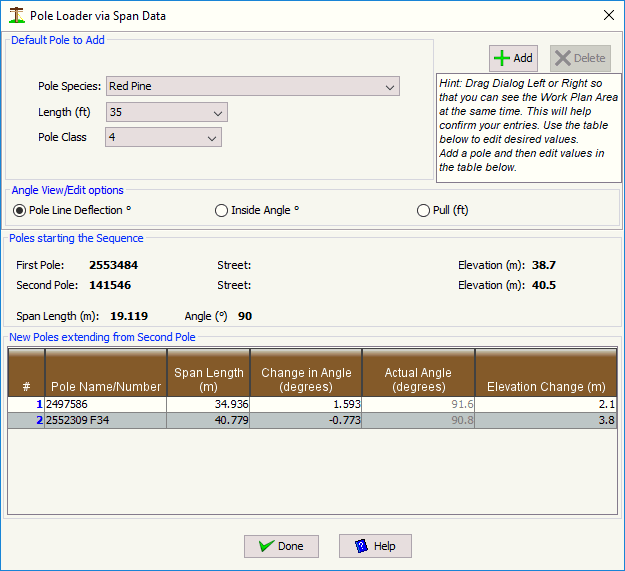
The middle section of the Dialog shows the first two poles that define the starting point and initial direction for the sequence. The third selected pole is included in the table to provide an example of how this sequencing will work.
New poles via the "Add" button will be added to the table based on the pole defaults show at the top of this Dialog. You can change these settings at any time while creating the desired sequence. The basic operation of this Dialog is to add new poles to the sequence and edit specifics in the Table. At the end of editing each field for each pole, the Work Plan is automatically updated. You may want to drag this Dialog to the side so that you can see the Work Plan and validate that it is doing what you intended as you enter data.
Fields:
- Pole Name/Number - This is the designation you will see everywhere related to this pole.
- Span Length (m) - Enter the distance from the previous pole to this one.
- Change in Angle (degrees) - This field will change based on the "Angle View/Edit" option chosen. Pole Line Deflection is also commonly called "Line Angle". Inside Angle is often provided by CAD systems. Pull is a another method that can be used. If the pole line is straight (tangent) to this pole from the previous pole, leave this field blank or enter a zero. If this pole is a corner pole, enter the amount of the angle in degrees that this pole deviates from a perfectly straight line based on the last two poles. Positive values will deflect the pole in a clockwise direction, while negative values will represent a counter-clockwise direction. Watch the work Plan Area as you enter each pole to confirm the result is what you intended.
- Actual Angle (degrees) - This is informational to show you the resultant angle of the individual span.
- Elevation Change (m) - Enter how high the base of this pole is above the previous pole. If the pole is lower than the previous, enter a negative number.
In addition to entering new sequences of poles, this same Dialog can be used to edit existing pole sequences. To do this, after you select your starting pole, select the whole range of poles that you would like to edit. You should know that the specific poles you select for the sequence must not include lateral/branch or other poles that are not part of a continuous line. Some checks and messages are generated if you selected an inappropriate pole. This feature can be used over and over again on the same or different pole line sections in your project. To assist with the later movement of poles, all connected anchors and buildings to the poles moved will be automatically adjusted by the same amounts. This retains the initially set span/lead lengths and angles.
Selection, Visualization and Connections
Selection
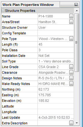
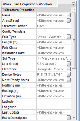
Selecting an item by left-clicking on it with a mouse will cause the Work Plan Properties window to be populated with various values or attributes for that item. Some of these items can be shown in a larger window if there is an “…” button at the right-hand side of the specific property. This is useful for text fields that are longer than what can be displayed in the space provided.
You can select multiple items by a couple of methods:
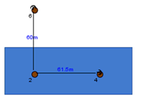
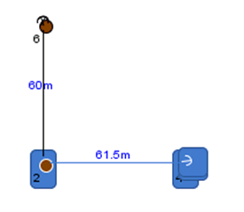
1. You can left-click the mouse at any point on the scene and then drag while holding the button down to another location on the scene. You will visually see a blue rectangle appear showing you the area of items selected. Once you release the mouse button, all items within the selected area will be selected. You can tell which items are actually selected since they will have a small blue rectangle in their background.
2. You can left-click the mouse on the first item to be selected. Then, while holding down the CTRL key, left click additional items. If an item becomes selected in error, click on it again while still holding down the CTRL key and it will be de-selected. This de-selecting method works if you first select items with option #1 above as well.
Once you have multiple options selected, the Work Plan Properties window will show you all the properties of similar names that are common to all of the items. For this (possibly) reduced subset of properties, there will be either a value shown that is common to all items, or it will display “Different Values” for the property setting.
Creating Span Connections
Once poles are located on the scene, you will first need to create a connection between two poles (or a pole and a building or long-span anchor) before you can add span attachments to them such as power conductors or messengers.
You do this by first selecting a pole. Then while holding down the CRTL key and the left mouse button, drag the mouse to the item you wish to connect. You will see a line and arrow appear at the end of where the mouse is pointing. When the arrow is touching the object you wish to connect, simply release the mouse button and CTRL key. Now you have established a connection.
You can now add attachments to this connection. Please note, if you haven’t added attachments to this connection before exiting Quick Pole and saving your project, you will need to create this connection again as it will not be permanently saved unless it has at least one attachment.
Visualization Rules:
On any connection that goes pole to pole, pole to building or pole to Long Distance Anchor will be visible, regardless of attachment types or distance.
Guy wires that go from a pole to anchor(s) will not be shown in most cases, except when the lead length exceeds 15 meters. At that point it is treated like a Long Distance Anchor.
Selection Rules:
To be selectable, Anchors must be further than 15 meters from a connected pole, or not yet be connected to any pole. Push Braces are never selectable in this View.
Connection Rules:
When making a connection from a pole, the only possible solutions are to other poles, buildings and long distance anchors.
Context sensitive menus will contain only the choices that are appropriate based on what is selected and what item you right-click to bring up the menu.
Structure Functions
Once you select a Structure (pole, building, long distance anchor), several options are available through a right-click of a mouse.
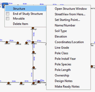
Open Structure Window
This function will bring up a separate Structure Window, enabling many Structure editing functions to be performed.
End of Study Structure
The "End of Study Structure" feature allows you to ignore the loading analysis for specific poles. For many projects you will need to place additional poles to the ones you may be designing in order to capture the proper span length and determine the loads. An example would be that you are attaching communication messengers to poles 2 through to 6, but other span attachments (such as power) continue to poles 1 and 7. You need to place poles 1 and 7 on the Work Plan so that Quick Pole knows the attachment loads in those directions related to poles 2 and 6. You are not normally concerned about the structural capacity of poles 1 and 7 as they are not related to the work you are doing. Providing Analysis Results for these poles will be distracting from the poles where you are actually doing work.
These additional poles (1 and 7) are required to define the loads on the poles you are really interested in, but you don't need to analyze them. By right-clicking on a pole in the Work Plan View, you can check the "End of Study Structure" checkbox. These extra poles will be listed in the appropriate reports, but without their loading analysis results. This feature allows you to focus on the more important items of your project.
Position Locking
Quick Pole is a GIS application with the added ability that it can be used in non-GIS situations as well. As a GIS application, the actual location of any item is usually fixed in the Work Plan. The location is then normally adjusted only by direct input of updated location information such as Northing/Easting or Longitude/Latitude. This can be done in the Bulk Location Edit Tool or one of the right-click options available.
When projects are first re-opened, the location of all items are "Not Movable" so as to prevent inadvertent movement by user actions. When new items are dragged from the Palette onto the Work Plan area, those items are movable until the next time the project is opened. Freehand movement is done by dragging the item with the left mouse button pressed. The Nudge tools at the top of the Work Plan Area are also available.
All or any item can be selected and have its Movable state changed so that it could be moved or fixed in place. You can right-click on any item and change its Movable State.
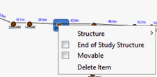
You can also select multiple items at the same time and change the Locked state of all poles, buildings and long distance anchors at the same time.
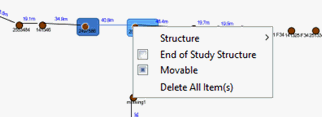
The CheckBox for the Movable State above is in an indeterminate state because some of the items selected are Movable and others are not. Selecting this menu item once will make these items Movable. Selecting the menu item a second time will make all items not Movable .
StreetView From Here...
If you have a Datum set for this project and you have set the GIS coordinates for at least one pole, you can use this menu function to launch Google Maps and StreetView in your Internet Browser (Internet Explorer, FireFox, Google Crome, etc). It first brings up Google Maps which then allows you to launch Google StreetView from the highlighted pole location by dragging the little person icon onto the map.
Mass Edit Structure Functions
Some of these functions are also available when two or more structures are selected at the same time. This enables setting more than one structure with the same data.
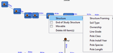
You can select multiple structures at the same time using the Rectangular Selection Technique or by holding the CTRL key down and left-clicking on additional items. Some menu items will be excluded from the normal list of menu items as they only applicable to individual items.
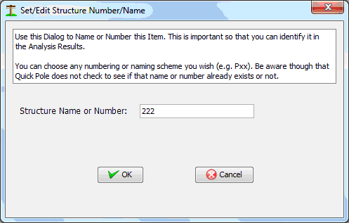
Structure Name/Number Function
This Dialog allows you to quickly just adjust the name or number designation for a structure. For Buildings you would normally put the name of the Business there. For poles, a pole number, etc.
Soil Type Function
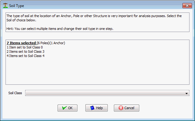
This function allows you to view or edit the Soil Type around this structure object, or multiple objects if initiated from the Work Plan area. The choice of Soil Type impacts the holding capacity of anchors and stability of poles. This is one of the functions that allow you to select multiple items at the same time and change the Soil Type for all items at the same time.
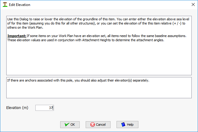
Elevation Function
This function allows you to set the absolute or relative elevation of a pole, building or anchor. Span attachments use the elevation of the base of the item along with the attachment height of the attachment to calculate the absolute vertical height difference between attachments on two separate structures.
For elevation you have the choice of entering only relative elevation differences from your lowest structure’s groundline, or entering absolute elevations above sea level. You must choose the method you want to use and be consistent across the entire project in order for analysis results to be accurate. Both negative and positive numbers are permitted.
Coordinates/Location Function
This function allows you to set the exact location of the structure item in the Work Area. The item will move automatically to the new location set in this Dialog after pressing the OK button. The Dialog explains that there are three different options for setting a structure’s location. The important thing to note is that Quick Pole internally uses Northing and Easting values for its span and angle calculations.
- Location based only on relative location on the Work Plan Area. This enables freehand location setting of structure items.
- Location based on provided Northing and Easting from survey data.
- Location based on GPS coordinates.
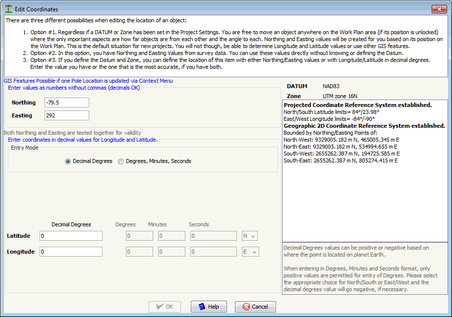
In options #1 and #2, you can only edit the Northing and Easting values.
Once a Datum and Zone are selected in the Project Settings tab, Quick Pole will test the coordinate values for all items in a Project to determine if they make sense with the Datum and Zone selected. If they don't, Quick Pole will display a message saying that GIS Features are possible if the coordinates of one project item is set. Quick Pole offers and expects to shift all project items so that their relative positions to each other are maintained while all items are moved so that they make sense with respect to the GIS coordinates supplied. Also this can be a great timesaver as you don't need to edit the other poles if their relative distances and angles were sufficiently accurate. You can, of course, double-check the other poles to see if their coordinates still make sense.

When reseting an item's coordinates once the GIS Features are enabled, this same question is asked. Select Yes to shift all project items; in case you have found a more accurately placed item. Otherwise select No to update just this one item.
The bounds of the defined Datum and Zone are displayed in both Longitude/Latitude and Northing/Easting values, for your reference. If you enter values outside of these bounds, the offending entries will be highlighted in red. If you believe you have the correct coordinates and still presented with errors, you may have selected an incorrect Datum and Zone. There is a tolerance on the coordinate entries to allow projects to extend slightly beyond the boundaries by about 10,000 meters. If you have a large project that extends outside of one zone by more than 10,000 meters, it is recommended to break the project into two separate projects.
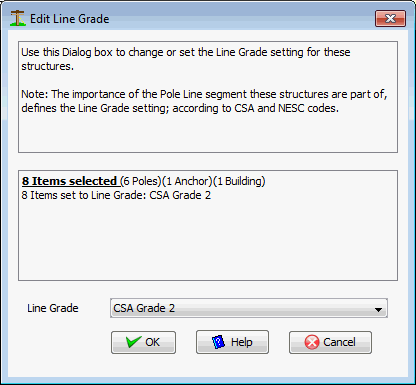
Line Grade Function
This function allows you to edit the Grade of the pole line at this point, or multiple objects if initiated from the Work Plan area. Often most of your project will be covered under one Line Grade with higher grades only required in special areas, such as in proximity to or at crossings such as railways. The Line Grade is used to determine the Overload Factors and Strength Factors required for each Structure and the standards base used (NESC/CSA).
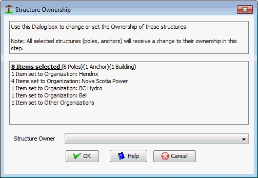
Ownership Function
This function helps to identify who owns the structure item involved or which set of Organizational Standards should be the most applicable. If initiated from the Work Plan Area, multiple selected items can have their Organizational setting changed at the same time
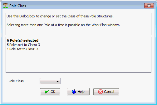
Pole Class
This Dialog allows you to set the class of one pole or multiple selected poles at one time.
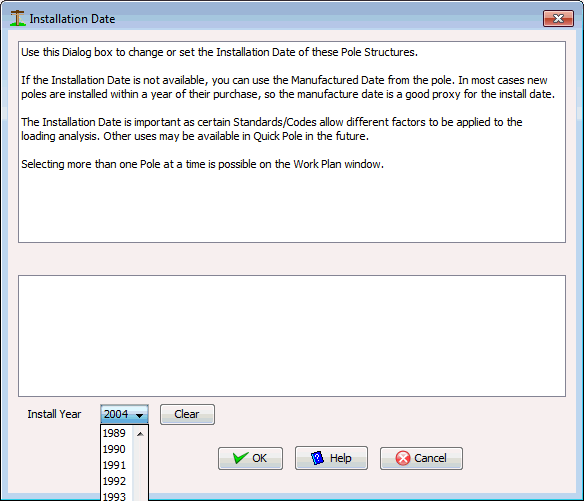
Installation Date
This Dialog is used to record the Installation or Manufactured Date of the pole. This may or may not have an impact on any changes you plan to make to the pole. This information is not mandatory, but will be included in some reports for informational purposes.
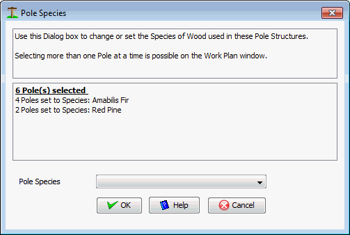
Pole Species
In this Dialog you can set the species of wooden pole used. One or multiple poles can be selected and have their "Species" changed at the same time.
Pole Length
You can use this Dialog to set the Pole Length of one or multiple selected poles at the same time.
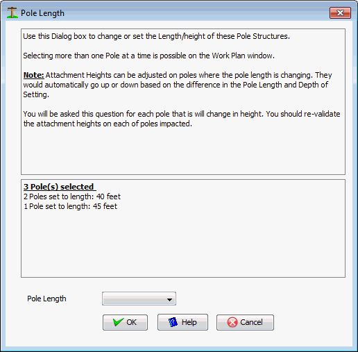
Changing the Pole Length from one size to another also often requires adjusting the attachment heights for all attachments by the net difference (pole length - depth of setting) for each pole (if applicable). This is expected to be a very common scenario where a pole line is first created in Quick Pole and then the pole is proven to need additional height for road crossings or other clearance issues. So automatically moving all attachments higher should be a time saver. If at least one pole has its length changed, a Dialog will pop up to ask you if you would like the attachment heights automatically adjusted for you.

This is always optional as there are some situations where you DO NOT WANT this to happen; such as when all attachment heights entered are confirmed correct but the pole length needs to change.
Design Notes Function
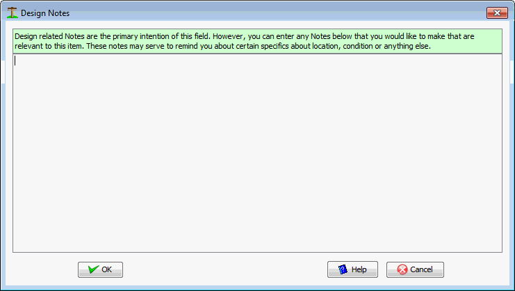
This function enables quick access to Design Notes about the structure item selected. You may want to record specifics about why you modeled this structure a certain way, or anything else you feel is warranted, related to the Analysis of the Structure. A separate notes setting is available to specifically capture Make Ready (Remedy) or Work Order notes. This ability is also available in the Structure Window.
Make Ready Notes
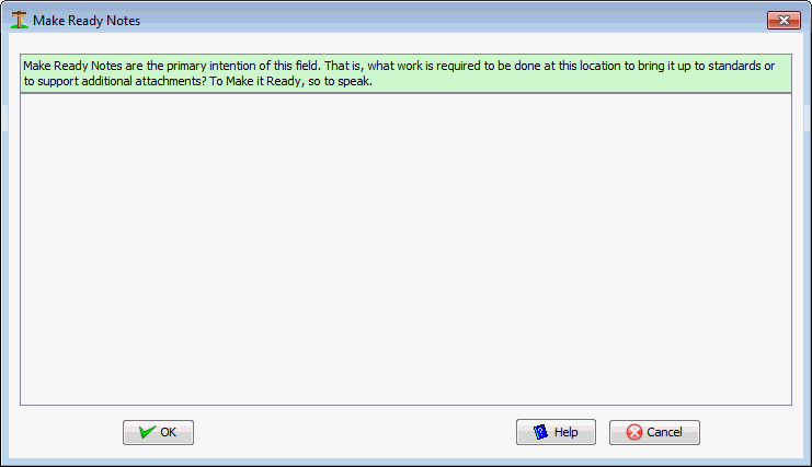
This function enables quick access to Make Ready Notes about the structure item selected. Here you can include any details about what changes are required at this pole. This ability is also available in the Structure Window.
Span Attachment Functions
From the Plan View, you can double-click on a span between any two items to bring up the Span Editor/Viewer window; where the majority of Span Attachment Functions are available. On a particular span, you can also right-click and select the Span Editor/Viewer option.
Multi-Span Profile View
There is a special Multi-Span profile view Dialog that can be helpful for visualizing many pole spans at once. It may prove useful for validation or documentation purposes. In many ways it is similar to the view in the Span Editor/Viewer Window.
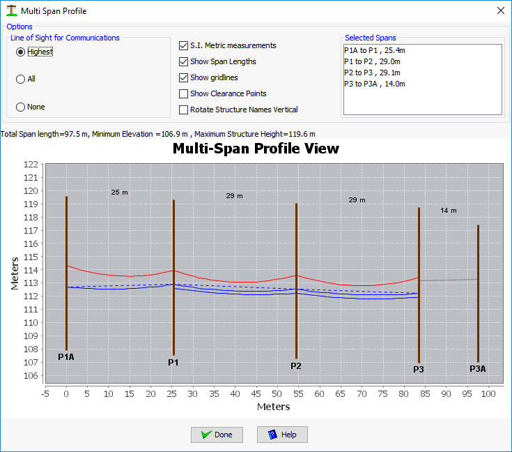
The process to get this view is very similar to the "Pole Sequence Edit" feature. It is a two step process. First you must right-click on the starting Structure and select "Set Starting Point". Then select a number of structures in the same pole lead (including the starting structure), and right-click on one of these structures. The following menu will show:
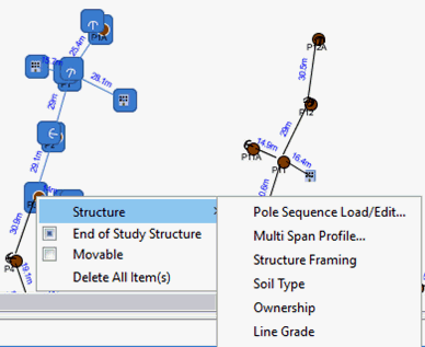
Select the "Multi Span Profile" option for the Dialog to appear. The controls on the Dialog are self explanatory and are there to help customize this view for you.
In the Work Plan View, you can right-click on a span and copy a whole category of attachments at the same time, or all attachments. The categories are :
1. Power Wires
2. Strands & Cables
3. All Attachments

The Copy Menu will have a submenu item for each category of attachments found to already exist in the span.
After copying they are placed in the Quick Pole's Clipboard for pasting elsewhere. There are a few ways they can be pasted. The first is you can right-click on a span and paste a single category of attachments or all attachments on the Clipboard.
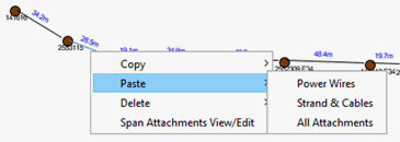
You can also select multiple spans in a row at the same time and right-click on a selected span to have the same pasting ability; but this time to all spans between the selected poles at the same time.

When attachments are pasted this way, the attachments are applied to the spans with the same framing/spacing as in the original span and are placed starting at the top of the Structure downwards. This enables poles of different lengths and depths of setting to look similar to how most poles would look in the field. After pasting the attachments, you should check the heights of all attachments against your field notes. In many cases they will be very close and this method will save you a great deal of effort.
Within the Span Editor/Viewer Window you have similar ability, except you can now select individual attachments as opposed to the entire category. You have access to the same Clipboard used in the spans. If items are on the Clipboard already when you first start, you will be told how many of the same category are available for pasting. You can copy any row to the Clipboard and paste it back to the same table as a duplicate. You can also copy one or two items to the Clipboard, close out of the Editing Dialog and have them available for pasting to one or more spans anywhere else in the project.
Pictures Window
This window allows you to store, view and inspect in detail, different pictures of the same pole. You can load as many pictures as you want here, however only the first eleven will be permanently recorded and re-displayed the next time you open this tab. One of it's main purposes is so that you can associate a number of pictures with one structure. As you assign pictures to this location, thumbnail views of these pictures will appear in the middle Tool Bar area. Selecting a thumbnail will cause a larger view of the picture to fill the Main Window.
In the Main Window it is possible to zoom in, out or pan from any location to better inspect details.
After selecting pictures, these picture locations will be stored against the structure/pole in the project. The next time the Pictures Window is opened with this structure selected, all pictures will automatically load once again. If you had rotated them to look better, these rotations will be remembered as well.
The first three pictures will be available for reports on this structure. There is at least one report (Pole Summary Report) that will look for these pictures. There may be others in the future, or created in response to customer requests.

It provides many standard "Viewer" and other functions:
- Add Pictures. You can select any picture that is accessible via a Drive letter (C:, D:, etc.) from your computer. Networked locations are available as well as long as they can be mapped to a drive letter in your Windows Explorer.
- Remove Picture. Simply select a picture in the list of thumbnails and press the remove picture button. This does not delete the picture, just un-associate it with this structure/pole.
- Order pictures to set preferred pictures for reports.
- Reset Zoom to Fit. Returns the size and position of the picture in the Main window to default.
- Rotate Left/Right. In increments of 90 Degrees.
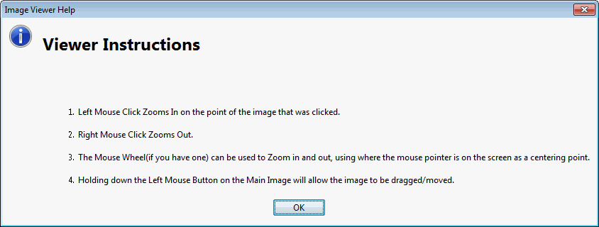
- Instructions. This shows a Dialog (below) that explains some of the Viewing Commands available:
Notes Window
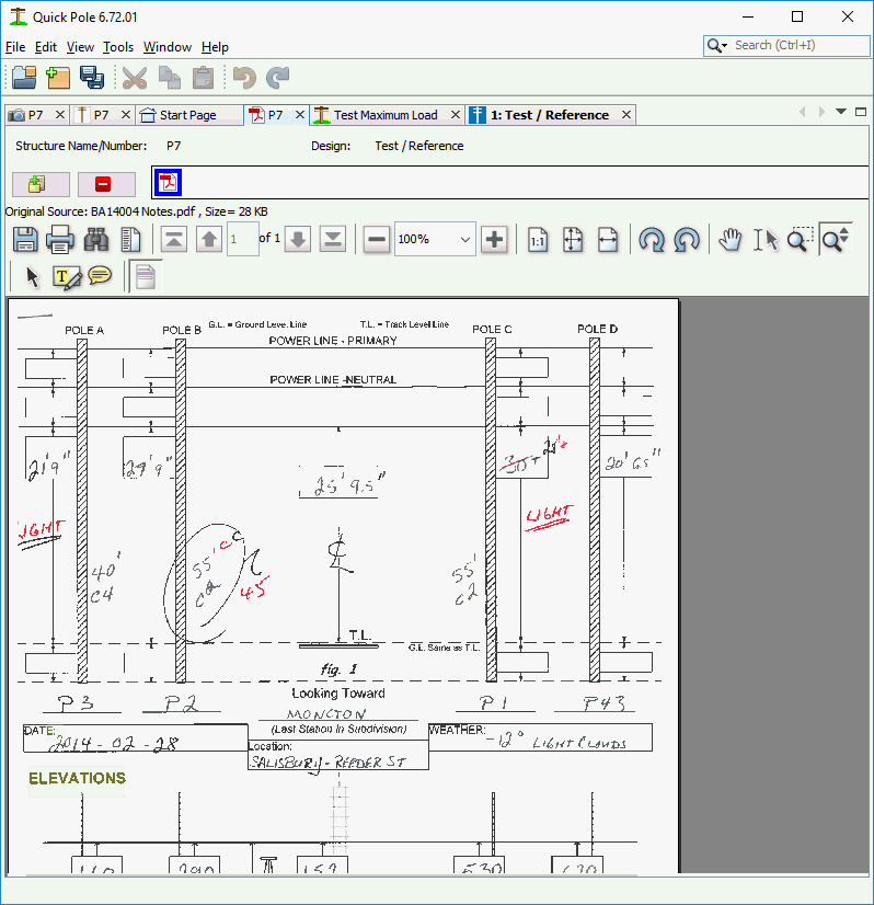
In this window you can store, view, print, zoom and perform a few other functions on many pdf files. Quick Pole will store and re-open up to five PDF documents the next time you open this window and select this structure. You can open and view more than five, but only five will be permanently referenced with this structure/pole. The main purpose is to support field survey notes scanned into PDF format plus other useful documents to assist the Designer. This enables several pieces of information that the Designer uses to be easily accessible from within Quick Pole.
This window works in a similar way to the Pictures Tab in that there is a button to add PDF documents and one to remove a document from the list. The Tool bar directly above the PDF document provides similar functions you would expect to see in a PDF Viewer and are self explanatory. If you place your mouse over any of the buttons, a description of the button appears as a Tool Tip.
Make Ready Manager
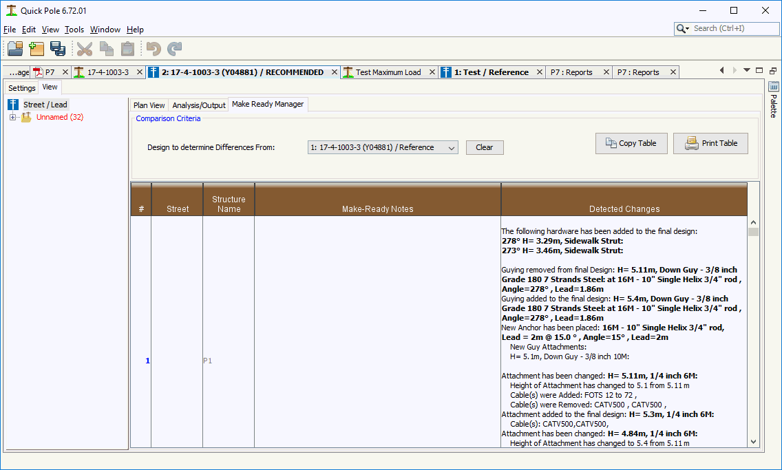
The Make Ready Manager is a way to compare the difference between two Designs in the same project file and show these differences alongside the Make Ready Notes already captured for each structure.
It is recommended that your first Design in your project capture ONLY the existing condition of the structures before your project. Then if you clone that Design into one you modify for your project (add strands,cables, guys, etc), then this comparison tool can help verify you have captured all required changes in the Make Ready Notes.
The Make Ready Notes can be edited right in this table.
Structure Framing Function
By selecting more than one pole structure at a time, you can choose to apply standard framing to these poles and standard wires between them. You can select the poles individually by holding the CTRL key down and left-clicking the mouse on additional poles, or you can drag a left mouse button down across a rectangular area to select many at once. This feature is best used for one pole line segment at a time and it will complain if it finds poles also selected in another lateral pole line.
Once the poles desired are selected, right-click the mouse over one of the selected poles and select the Structure Framing menu item. It will start a wizard that will guide you through a few questions to be answered before automatically framing and wiring your selected poles. This feature is geared towards Power Wire Framing. As part of this process, all existing Power Wires and crossarms will be deleted from the existing poles before placing the new Power Wires and associated support hardware.
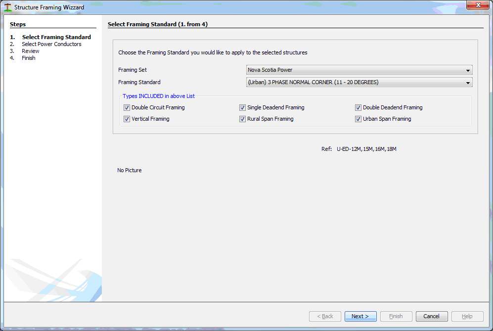
As the first step you are asked to select the type of framing you would like to put on these poles. These framings are either already in the database for you to use, or you can enter your own through the Data Manager. Framing Standards are stored in the database by Organizational grouping first and then by name. You can filter the list of framings to choose from within an Organizational set by deselecting one of the Framing type Check boxes. As you select different Framing, a picture of the framing and a list of applicable framing references will be shown in the bottom half of the Dialog; if they were populated in the database.
The next Dialog allows you to set the type of Power Wires you want to use.
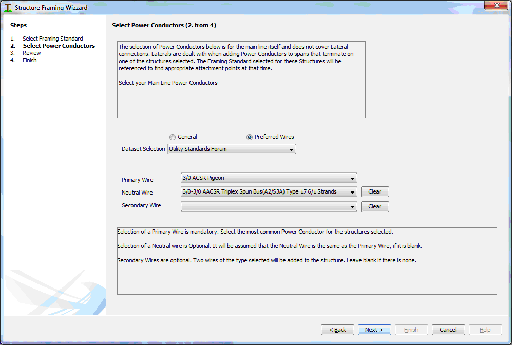
As with other places in Quick Pole where you can select Power Wires, you can choose from Preferred Wires that already have tensions defined for them, or you can select from a General list of wires. Entering a Primary Wire is mandatory. If a Neutral Wire is not defined, it will assume it is the same type as the Primary Wire. The Neutral Wire can be a combined Neutral/Secondary Wire such as in the case of Spun-Buss, or any other wire of your choosing. If Secondary Wires are chosen, two of these wires will be placed onto the pole in Open Buss Secondary style.
The Next Dialog shows you a review of what poles and span will be affected, for confirmation before any changes are implemented.
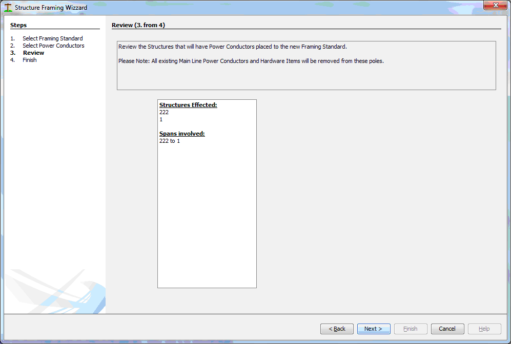
Pressing the NEXT button will implement all the changes.
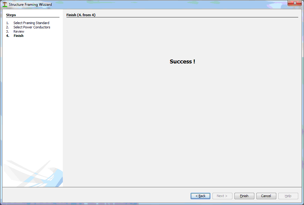
And the final Dialog confirms if implementing the changes were successful or not.
Created with the Personal Edition of HelpNDoc: Generate EPub eBooks with ease
