Data Manager
Data Manager Overview
Quick Pole comes pre-loaded with a lot of information "Out of the box" to help you get working as soon as possible. Quick Pole uses an internal SQL compliant database to hold all this information so that you can operate Quick Pole in the field without access to the Internet. The Master Dataset and an Example Power Utility are managed by Sonideft, while most Datasets are created and maintained by the User Community themselves. Quick Pole encourages users to share Datasets amongst yourselves, plus we offer to post a Dataset on our website in the public domain to make sharing easier.
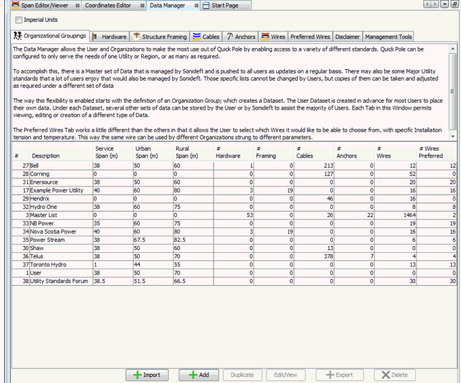
Quick Pole makes it easy for you to:
- Create new Datasets holding organizational standards
- Duplicating existing Datasets in order to start making changes to a copy
- Edit existing Datasets
- Export a Dataset into a file for sharing with others
- Import a Dataset provided by another source
- Delete a Dataset that you no longer require.
At the top of this Tab is a CheckBox for selecting the type of units that you wish during view or edit functions: Metric or Standard (feet, inches, pounds...). When you first open the DataManager, this CheckBox is set based on the Preferences you have set for yourself. Changing the setting in the DataManager will not change your permanent preference settings. Based on this setting, the DataManager tabs will show their information in the units selected. Likewise, any detailed editors or viewers will use this setting when they are initially displayed; which can be adjusted separately with respect to units desired.
Each Window Tab in the Data Manager manages a different type of data, for all Organizational groupings.
- Organizations
- Hardware
- Structure Framing
- Cables
- Anchors
- Wires
- Preferred Wires
- Disclaimer
- Management Tools
Organization Groupings
For maximum flexibility, all sets of information are organized by Company or Organization.
This Window Tab starts by presenting a listing of the different Organizational Groupings stored in Quick Pole's database. For each Organization it provides some basic statistics on the number of data items stored, how many projects reference them and some quick information on span length settings. The User category is preloaded just for you to store anything you wish for your own personal or temporary use.
If the Organization is "Master", it is managed by Sonideft and you will see the "View" button enabled. Otherwise the same button will show and allow you to "Edit". Add and Edit provide the following Dialog for changes. Using the View button produces the same Dialog except changes are not permitted (read-only).
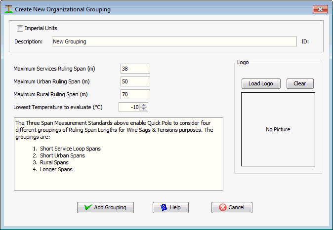
The three span measurements are used in conjunction with Preferred Wires for this particular Organizational Grouping. They represent the maximum span lengths that are associated with different stringing tensions of the item. The "Lowest Temperature to Evaluate" represents the lowest design temperature you wish to use in your evaluations. The lower the temperature, the higher the maximum wire tensions will become. Quick Pole defaults to -30°C. In general customers in Northern climates will want lower temperatures for this value than customers in Southern climates, relatively speaking. The "Load Logo" button is used to load a corporate or Organizational logo, which is useful for different locations of Quick Pole..
Hardware
The Hardware Window Tab is used for all hardware and equipment items you may want to attach to a pole. Any item under any Organizational Grouping is available to use in your projects. There are no restrictions related to Pole Owner or otherwise.
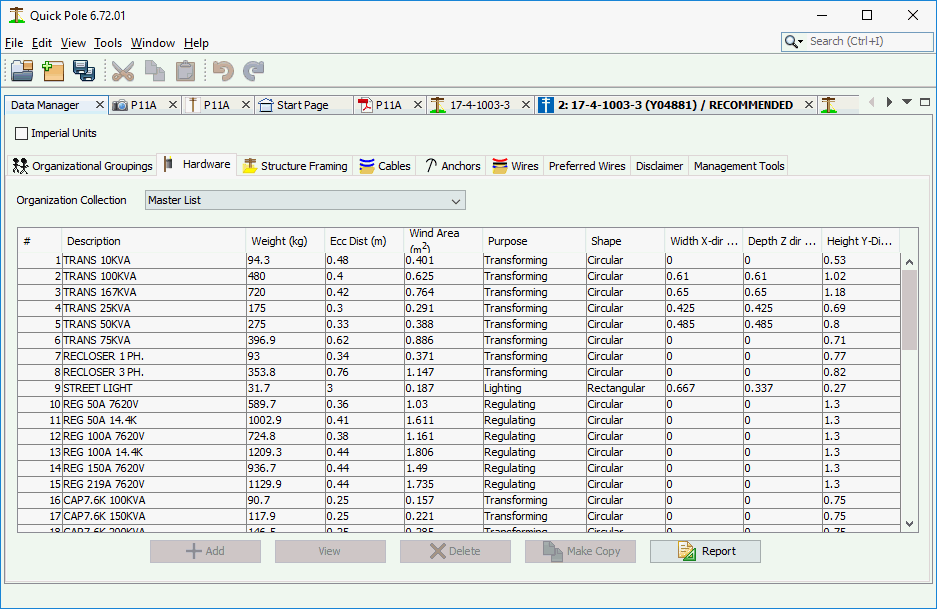
The table listing will change for each Organizational Grouping you select from the Drop-Down list of choices at the top of the tab. By pressing the "Report" button you can generate a report you can print or export to PDF or Excel (for example) on all the Hardware items stored in the database; within this Organizational Grouping only. Only a subset of information is shown in the listing. You can scroll through the list and select the item you want more information about or want to Edit. If the item is managed by Sonideft, you will only be able to View the information. The "Make-Copy" button is useful to copy an item from the current dataset into another; perhaps with some slight changes.
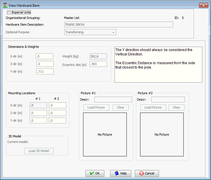
The data attributes are defined as follows:
Hardware Item Description
Enter whatever description you feel best describes the item.
Purpose:
Selectable values are Structural, Regulating, Transforming, Lighting. This is handy for sorting the hardware listing as the table column heading will sort the list for you if you click in them.
Dimensions and weights:
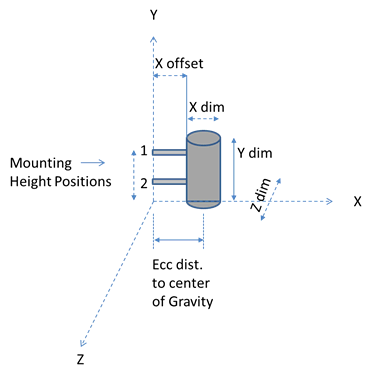
Hardware items are measured and stored as if they are positioned on the X-axis as shown below. Either the bottom of the hardware will be resting on the X-axis, or its mounting hardware. In specific projects you will be able to change their actual height and angle of attachment. Prior to editing any of the hardware's attributes, select the most appropriate "Purpose" from the drop-down choices.
The length, width and height basic dimensions of the item are fairly self explanatory. Enter these while also selecting the item's "Shape". The Eccentric distance is the distance to this item's center of gravity from the side of the pole to which it is mounted. In the case of items extended on long brackets that are not perfectly horizontal, you may also have a similar measurement called "Y offset" to enter. This tells Quick Pole the height of center of the equipment at the end of the long bracket. This value is used for both wind and center of gravity purposes.
Most pieces of equipment will have at least two locations that are used to secure the equipment's mounting bracket to the pole. Enter the vertical height above the bottom of the equipment or of the mounting bracket for each mounting position. The top mounting position is assumed to carry all the required loads onto the pole. This is not always true, but is on the safe side of assumptions for pole loading calculations.
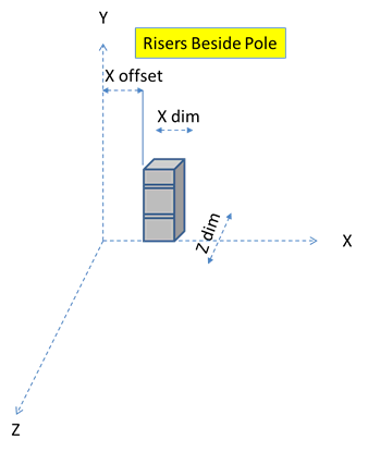
Some equipment will utilize stand-off brackets or other similar methods of installing the equipment away from the pole. This is called the "X-Offset" and is measured between the face of the pole and the side/edge of the equipment.

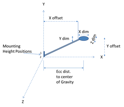


Insulators can have a stand-off bracket with a specific X and Y offset, plus an angle measured from the horizontal. This is typical of side-mounted insulators. The insulator itself would have a defined length, diameter and voltage rating. The voltage rating is for phase to ground voltage values, not phase to phase which are about 1.8 times phase to ground values. For convenience, the data for the stand-off bracket (if present) is entered with the insulator data so that it can be applied to projects as one unit. Since different mounting options are possible, the eccentric distance is entered for the insulator only and does not include the mounting bracket effects.
3D Model
Use this feature if you have a 3D model of the hardware item to use for visualization.
Pictures
You can load up to two pictures for each hardware item, with description. Possibly from different angles.
Structure Framing
Quick Pole can use Framing Standards within an Organization to help populate several poles at once with Power wires, support hardware such as crossarms, neutral wires and secondary wires.
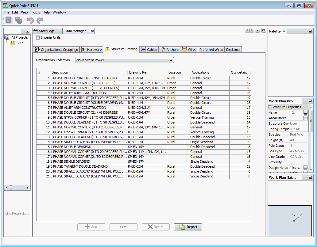
The listing shows the different Framing Standards available for use in Quick Pole, drawing reference numbers, application and the number of framing details associated with the standard.
The Report button will create a Report on all Framing Standards within the Organizational Grouping being displayed.
If you are in an Organizational Grouping that you don't have permission to change, there will be a "View" button enabled at the bottom of the Window. Alternatively there would be an "Edit" button, and the Add button would be enabled. View, Edit and Add buttons display a Dialog with the same fields as follows:
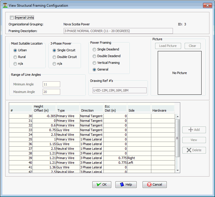
Framing Description
Enter the name of this Framing Standard that would make sense to you or your users.
Most Suitable Location
This value is related to the different span lengths used for Preferred wires in an Organization. Urban areas would normally use Framing Standards that support either Urban or Rural span lengths. Rural areas should not normally use Urban Framing Standards as they may not be strong enough. Select from Urban, Rural or not applicable.
3 Phase Power
If the framing is for 3 phase, you can select that it contains one or two 3 phase circuits. Single phase framing would be n/a.
Power framing
This is primarily for sorting purposes, but also to help you find the framing standard you want.
Range of Angles
Enter the applicable line angle for this type of construction. If this is for a tangent pole line only, enter 0 for both entries. Otherwise define the minimum and maximum intended line angles.
Drawing References
Enter here the applicable standard references within your Organization. Note that Quick Pole Framing can address a few different applications using the same basic definition.
Picture
Enter here a drawing or photo of what this Framing Standard looks like.
Table of Items
This table contains all the detailed separate items associated with this Framing Standard. It includes the items required to frame the basic pole, plus it should include how single and 3 phase laterals should be addressed when they come off this pole. In addition, all preferred guying locations should be indicated at the same time for the basic pole (on a corner) and the laterals.
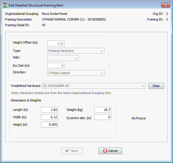
Each individual Framing Item can be viewed, edited or added depending on your permissions. The fields are described as follows:
Height Offset
Enter the distance from the top of the pole downward.
Type
Select from Primary Wire, Neutral Wire, Secondary Wire, Guy Wire, Framing Hardware or Other
Side
Enter the side of the pole when viewed facing the next pole in the line
Ecc Dist
If the item is held to the side of the pole (on a crossarm for example), enter that distance here.
Direction
This is really how different applications get applied to the same pole. Normal Tangent includes corner poles, 1 phase lateral, 3 phase lateral, Inline Deadend T (for towards next pole), Inline Deadend A (away from next pole) are the choices.
Predefined Hardware
If the line item is for Hardware, choose an item from the drop-down list. Only hardware already defined in the same Organizational Grouping is available.
Dimensions, Weights and Picture
If a Hardware item is chosen, all of these items are displayed from values in the database.
Cables
Cables are defined in Quick Pole as items that can be attached to wires. Cables have many of the same characteristics as Wires, but are not expected to support their own weight over long distances, such as between poles. For that purpose, the Wire type has all the required parameters to estimate their behavior. Quick Pole supports cables designed for either Power System and Communication System purposes. In both cases, many of these cables have components that help provide strength to the cable that is significant enough to affect the resulting Sag and Tension of a supporting wire. To cover all scenarios, Quick Pole enables two separate strength materials to be present within the cable which can be modeled and included in any Sag & Tension calculation. The strength components are not expected to be major contributors, but contributors none the less. For this reason the full polynomial modeling of two materials (such as for wires) is not required. A constant Modulus of Elasticity is used in cables for each strength component, each with their own coefficient of thermal expansion and effective cross-sectional area.
Self supporting cables such as ADSS, Figure 8 and OPGW are actually categorized as wires, since they can be strung by themselves. Several categories of Communication Cables are available in the Master Organizational Grouping, including some Generic sizes for when you only have a bundle size to work with.
In order to assist in browsing through the listing of cables, you can double-click on any column heading to sort the whole table based on that column's value. Double-click the same column a second time and it sorts it in the reverse order to what was displayed previously.
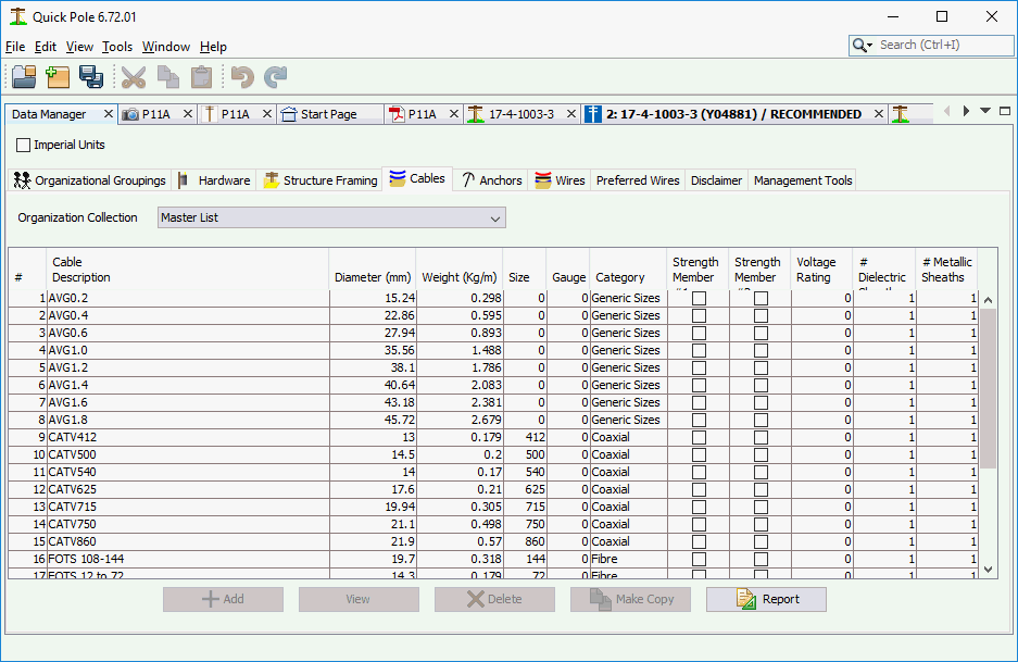
The Report button will create a Report on all Cables within the Organizational Grouping being displayed. The "Make-Copy" button is useful to copy an item from the current dataset into another; perhaps with some slight changes.
If you are in an Organizational Grouping that you don't have permission to change, there will be a "View" button enabled at the bottom of the Window. Alternatively there would be an "Edit" button, and the Add button would be enabled. View, Edit and Add buttons display a Dialog with the same fields as follows:
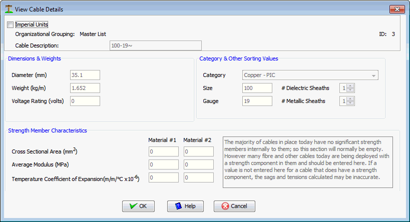
Cable Description
A description useful to identify this cable
Diameter
The diameter of the cable
Weight
The weight per unit length of this cable
Voltage Rating
The breakdown voltage rating for this cable.
Category
Choices are: Not Categorized, Generic Sizes, Paper/Foam, Copper Grease-filled, Copper - PIC, Copper - Lead Sheathed, Coaxial and Fibre
Size
Enter a value useful for sorting cables of this type. Could be number of glass fibres, copper pairs, coaxial diameter, etc.
Gauge
To assist with the sorting of copper cables, you can enter the gauge of the copper pairs here.
# Dielectric Sheaths
This represents the number of dielectric cable sheaths present in this cable. This value would be apparent from the manufacturer's cable data sheet.
# Metallic Sheaths
This represents the number of metallic cable sheaths present in this cable. This value would be apparent from the manufacturer's cable data sheet.
Cross Sectional Area
Valid only for Cables with a strength member and the cable is restricted from moving longitudinally. The cross sectional area of the cable's strength member, or aggregate of their total areas.
Average Modulus
Valid only for Cables with a strength member and the cable is restricted from moving longitudinally. The modulus of elasticity of the cable's strength member.
Temperature Coefficient of Expansion
Valid only for Cables with a strength member and the cable is restricted from moving longitudinally. The rate of expansion of the cable's strength member (s).
Anchors
Anchors in Quick Pole are defined as items placed into soil/rock that enable the attachment of guy wires for the purposes of supporting tension forces. Most anchors you will need will come from the Master Organizational Grouping, but you can select from others or enter your own under the User Organization.
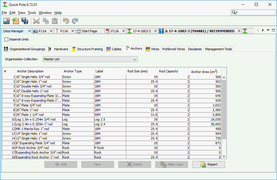
The Report button will create a Report on all Anchors within the Organizational Grouping being displayed. The "Make-Copy" button is useful to copy an item from the current dataset into another; perhaps with some slight changes.
If you are in an Organizational Grouping that you don't have permission to change, there will be a "View" button enabled at the bottom of the Window. Alternatively there would be an "Edit" button, and the Add button would be enabled. View, Edit and Add buttons display a Dialog with the same fields as follows:
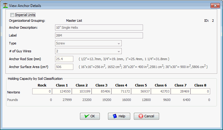
Anchor Description
A description for the anchor which helps it be found later
Label
A small amount of text that will be used for display purposes on the Work Plan and other locations
Type
The type of Anchor. Available choices are Plate, Screw, Log, Rock and other. Screw anchors describe the Helix anchors that are normally screwed into the soil with machines.
# of Guy Wires
This is for the maximum number of guy wires that are permitted to be attached to the end of the anchor rod.
Anchor Rod size
Enter the diameter of the rod in millimeters.
Anchor Surface Area
The amount of surface area of the anchor available to hold against the soil. For log anchors, this would be the diameter times the length; not the actual surface area.
Holding Capacity
Enter the Rated capacity of the anchor and rod combination for each Soil Class. Enter 0 if not applicable or essentially no holding strength.
Wires
Wires in Quick Pole represent virtually anything that can be strung between two poles or between poles and a building. They can all support their own weight and some of them can support the weight of Cables as well. There is a wide assortment of wires stored in the Master Organization collection of many different types. If you go to the Select Wire/Cable Type Dialog for any wire attachment between poles, you will see all of the different wire categories available in the database. At time of writing, there were 22 Power wire categories (including aluminum, copper, steel core, multiplex and Spun Buss varieties), four (4) steel wire rope categories, two(2) Figure 8 categories, Optical Guy Wire (OPGW), All Dielectric Self-Supporting (ADSS)Cables and Communication Wires. Over 1400 individual wires on file and maintained by Sonideft.
In addition to the database storing the basic wire data you would expect, it also contains the elasticity and creep polynomials for two separate strength components in each wire. This way the full non-linear characteristics of the wire can be modeled for accurate Sag and Tension calculations.
Some wires are strung with cables attached either through the use of spacers of from the wire used as a messenger, or by plastic extruded over both the wire and cable so they become one unit. These cables are termed "composite" cables and include as examples: Figure 8 cables and Hendrix cables.
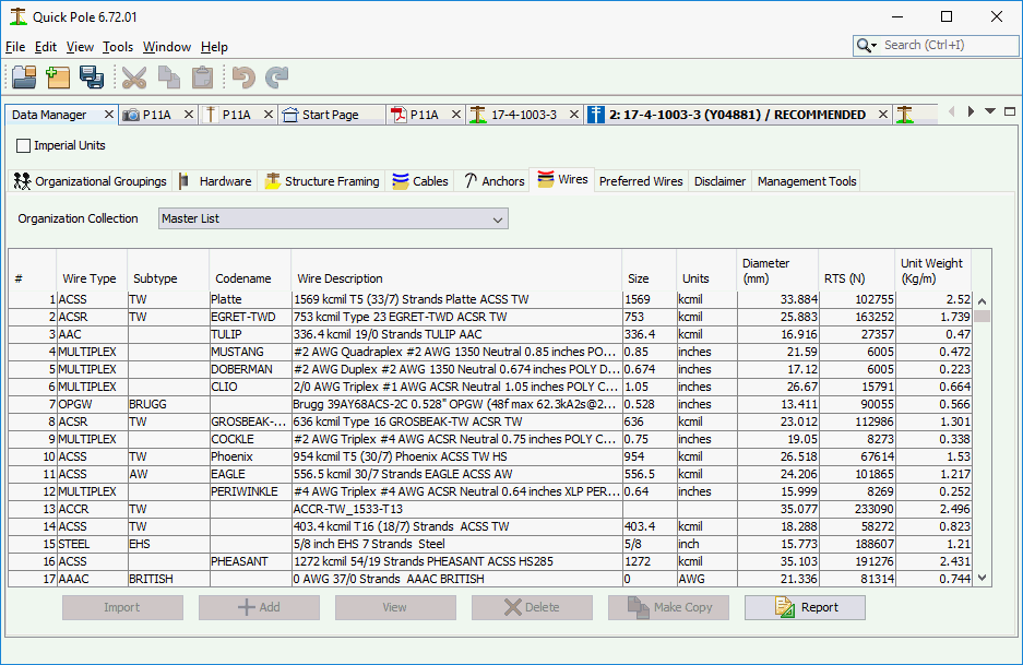
The Report button at the bottom of the Window produces a Report containing all wires within the Organizational Grouping shown, sorted by Wire Type. The report will be created and shown within the System Reports Window Tab.
The Import button enables you to add one or more wires into the database.
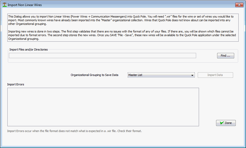
To use this Import feature, you must have the wire data available in .wir file format. This is the same format that most manufacturers provide so that the wire can be imported into PLS-CADD.
Step 1 is to use the Find button to find the file or directory of files.
Step 2 is to select the Organizational Grouping you would like the wires to be imported into.
Step 3 is to push the "Import Data" button. The large message box will show you the progress and any errors it encounters. If there are any errors in the format or contents of the .wir file, the wire it had an error with will be in the message box. Be sure to scroll through these messages to find any errors. If an error is found you have the options of:
- Editing the .wir file directly to correct errors
- Request a new .wir file from the manufacturer
- Add the Wire manually, using the existing .wir file as a guide to the values. This option is the least desirable as it is prone to input errors. If this option is chosen, compare a successfully input .wir file with the one you have and its inputted data.
Step 4. It is very important to ensure that the "Type" and "SubType" fields have been detected properly. If these are empty or do not match others in the Master Database, they will not be available for use in your projects. The spelling must be exact. Uppercase is preferred, but not mandatory. As an example, ADSS cables will never have these fields populated as part of the import. Type and Subtype are fields that Sonideft has included into the Quick Pole database which are not part of the .wir file format; although many (not all) are interpreted for you.
The "Make Copy" button at the bottom of the screen allows you to select a wire in the table listing and make a copy of it with modified parameters (name, diameter, etc) and to restore it in the same Organizational Grouping. The functionality is very similar to use of the Add or Edit buttons, except that the input data to start editing comes from another wire.
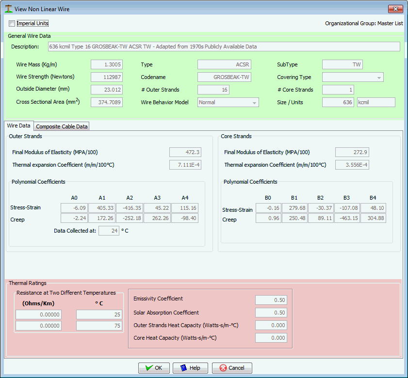
The first tab in this Dialog contains all the detail data required for the "wire" component only, as follows:
English Units
Select this Checkbox to enter/edit all these values in English or Metric Units.
Description
Enter any description you think is appropriate to find this wire.
Wire Mass
This is the weight of the wire per unit length.
Wire Strength
Rated Tensile strength of the entire wire
Outside Diameter
The overall diameter of the outside of the wire
Cross sectional area
This is the total cross sectional area of all strength components of the wire. For example, for ACSR wires you would add the cross sectional areas of both the steel and aluminum components to enter her.
Type
Enter one of the Wire Type categories discussed earlier
Codename
Enter a codename, nickname or any other short familiar phrase normally associated with this wire. This entry can be empty
# Outer Strands
The number of individual strands on the outside of the wire
Wire Behavior Model
Most wires would use the "Normal" option, but "GAP" is also available for wires with two strength components of different characteristics. GAP wires are designed so that there is minimal friction between the inner core and the outer wires. This enables both to expand and contract independently. Also, when the wire is initially strung, all tension is applied to the steel core alone. The end result is a wire that has less sag at high temperatures because the sag becomes dependent on the thermal characteristics of the steel core alone; which expands less than aluminum.
SubType
For greater clarity, some Wire Types have sub-categories. Enter the subtype, if applicable
Covering Type
The choices are none, POLY or XLP. None would represent a bare wire, POLY or XLP would be for a plastic covered wire
# Core strands
The number of individual wires in the core of the wire.
Size/Units
Mainly for sorting purposes, enter the size amount and the units of the size.
Outer and Inner Strands
Enter this section as per manufacturer's instructions. If there is only one type of metal in the wire, enter this information in the OUTER wire section.
Thermal Ratings
Enter this section as per manufacturer's instructions.
Composite Cables
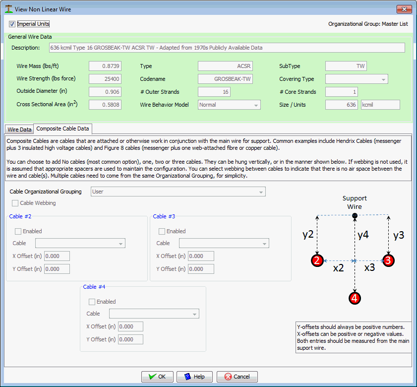
The Second Tab "Composite Cable Data" enables you to View or Edit up to three separate cables attached to this wire. For simplicity, all cables attached must be selected from the exact same Organizational Grouping. Since most real examples of these wire/cable combinations use the exact same cable multiple times, this shouldn't be an issue. If it is, copy all cables required to the same Organizational Grouping first.
The "Cable Webbing" option is used to describe cables that are integrally linked with the main wire, such as when plastic is extruded over both the wire and cable. Figure 8 cables are an example of this and would typically be implemented by enabled one cable with zero distance offsets along the Cable Webbing CheckBox selected.
Preferred Wires
Preferred Wires are Wires like any other Wire in the Database, except that these wires are configured specially for how the Organization wishes to use them. Specifically, Preferred Wires point to existing wires in the database and store stringing tensions specific for the Organization. The principle is that many Organizations can purchase and use the exact same wires, anywhere in the world. The tension that these wires are strung to under everyday conditions will vary based on temperature and storm conditions, plus adjusted to achieve specific objectives of the Organization. For instance, one organization may be concerned about aeolian vibrations whereas another may be concerned about high temperature sag. Based on what the most important aspect related to tensions is for an Organization, they can use the exact same wires as another Organization with different stringing tensions.
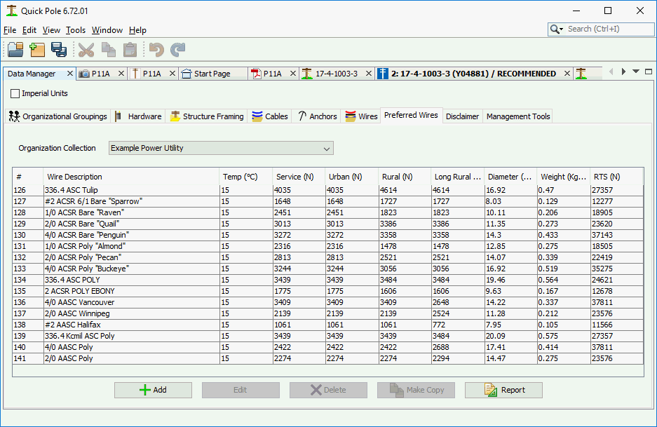
The Report button will create a Report on all Anchors within the Organizational Grouping being displayed. The "Make-Copy" button is useful to copy an item from the current dataset into another; perhaps with some slight changes.
The span measurements related to tensions are defined once for all Preferred Wires that an Organization uses. These are set under the Organization Tab.
For a constant installation temperature, you set a stringing tension for each of the possible span lengths. The "Service" category is mainly used from a pole to a building/home and represents the lowest stringing tension for this wire. Some attachments can be forced to use this tension option even though the actual span length may be more than the defined Service Span length. Urban tensions are meant to cover situations where "Urban" style pole framing is involved. Likewise, "Rural" framing typically involves stronger framing such as crossarms. In some cases, very long span construction may require higher tensions in order to meet sag conditions; as a standard. In most cases the actual stringing tension can be over-ridden for span attachments. The tensions meant to be stored in the database here should best represent "Standard" tensions and normal work Methods.
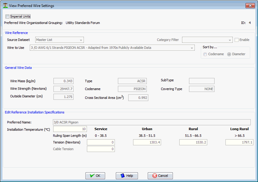
When you create a new Preferred Wire for an Organization, the first thing you do is to find the actual wire you want to use within the Master Organizational set of data. The Category Filter can be used to help narrow your search for the right wire.
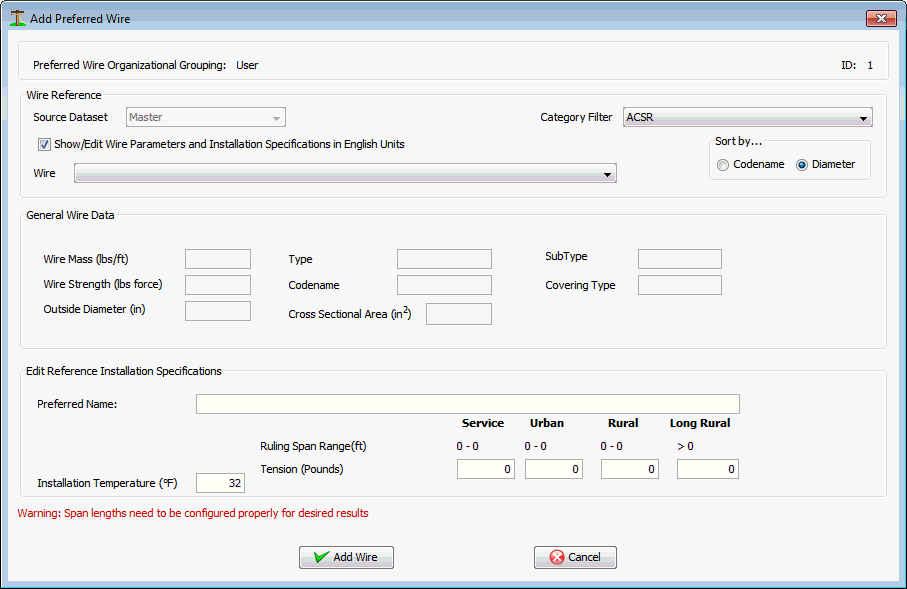
The General Wire Data section will be filled in to help ensure you have selected the wire you want.
The Preferred Name for this wire is what your Organization would normally call this wire. Enter anything you wish here.
Enter your installation tensions and the ambient temperature that correspond to those tensions.
Disclaimer
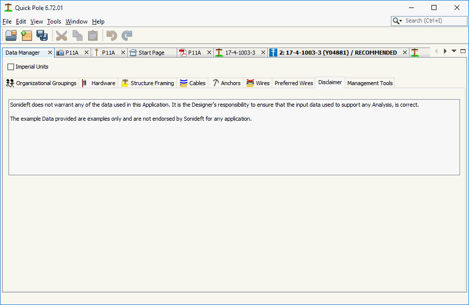
Fairly self explanatory. While Sonideft makes an attempt at providing data to support the analysis of pole lines that is reasonably accurate, there is no way we can guarantee their absolute accuracy. We are highly interested in providing users access to the most accurate data and want to support the User Community in maintaining this data for the benefit of all users. However, users must take full responsibility for the data they use inside and with Quick Pole.
Management Tools
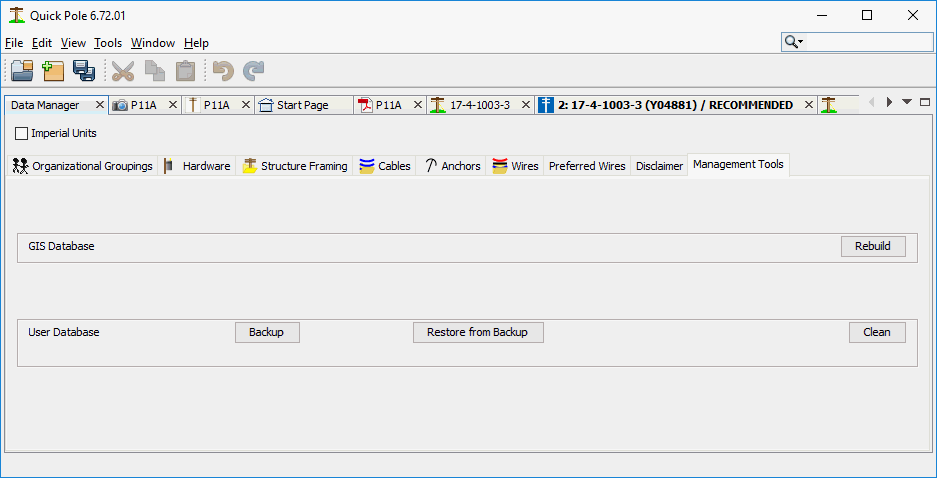
In this tab, various Data Management features are provided for use by the User or with the assistance of their IT Support Group. It is advisable to close any open projects before performing any of these functions.
GIS Database:
In the remote chance that something corrupts the database that Quick Pole uses to provide conversions between different Datums and Zones for GIS purposes, the "Rebuild" button will re-create the GIS database from scratch. This can be used with Quick Pole running with no impact or loss of data.
User Database
- Clean will erase everything in your current User database related to wires and materials you have stored for yourself. Then it recreates a clean fresh User database to start anew. This is permanent and cannot be undone. The User database includes any imported databases, meaning that these will need to be re-imported after the cleaning. You should make sure you still have a copy of any needed databases to import before starting this procedure.
- Backup - takes a copy of your User database and creates a zip file that you can store anywhere your computer can access.
- Restore - restores a previously backed-up copy of your User database. It will over-write anything you currently have in your database.
Created with the Personal Edition of HelpNDoc: Create iPhone web-based documentation