Structure Window Overview
Structure Window Overview
This function enables a wide range of Edit/View/Analyze/Report capabilities that can be done with a structure. This window can be reached by the right-click menu for a Structure on the Plan View, double-clicking on that same Structure, or through a right-click on the Structure in the Analysis Tree. There are three separate tabs in this window. The first covers a lot of information about this pole and the second allows modification and addition of various attachments, equipment and guying. The last tab is where the Structure can be analyzed separately from the entire project. Included are messages, reporting and a graphical display of the results.
There will be only one Structure Window created inside of Quick Pole. This window, once opened, will be updated to reflect the current selected Structure.
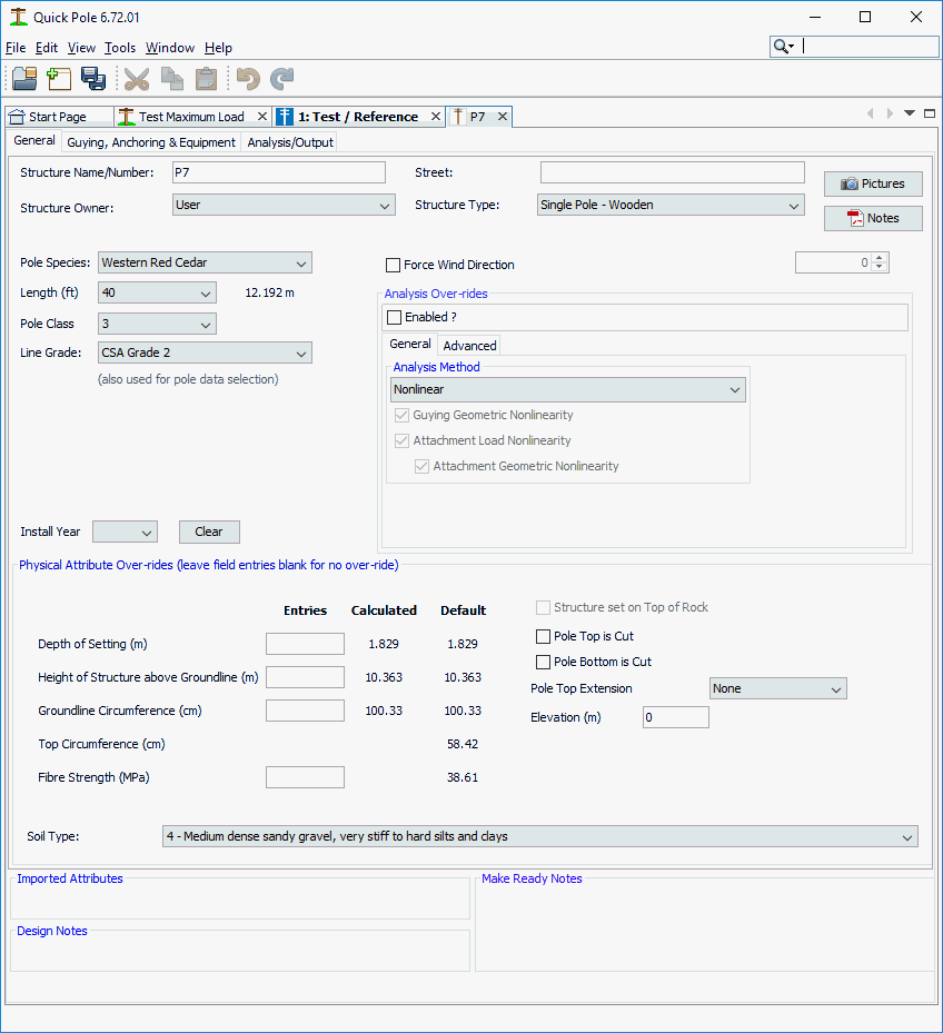
General Tab
Structure Name/Number:
Enter or change the designation for the pole.
Street:
Street or road names are useful here to help locate the pole later in Reports.
Structure Owner:
You can choose from any of the previously defined Organizations via the Data Manager.
Structure Type:
Only Wooden Poles and Concrete Poles are enabled at this time, however steel and composite poles are envisioned for a future edition of Quick Pole. Different manufacturers of Concrete poles are treated like separate species for wooden poles, in that different dimensions (internal and external), modulus of elasticity and strength are possible. If you don't see your desired manufacturer listed, simply find the required physical parameters for the manufacturer's poles and forward to Sonideft for inclusion in the next release.
Pole Species:
The species of the wooden pole can be selected from the full list of wooden pole species available in ANSI 05.1.
Length:
In feet, pole length choices range from 25 to 100 feet. Changing the Pole Length from one size to another also has the added feature of optionally adjusting the attachment heights for all attachments by the net difference (pole length - depth of setting). This is expected to be a very common scenario where a pole line is created in Quick Pole and the pole is proven to need additional height for road crossings or other clearance issues. A pop-up Dialog will appear to ask you if you wish this to be done for you. Automatically moving all attachments higher is expected to be a time saver, most of the time. A note appears in the Dialog to remind users that they should re-validate the desired attachment heights.
Pole Class:
Classes H1-H6 and classes 1-7 are available choices.
Line Grade:
Select the highest Line Grade appropriate for where this pole is located or in proximity. This setting indirectly also sets whether the CSA or NESC standards will be applied to this pole.
Install Year:
If you know the year or manufacture date of the pole, select the appropriate year from the drop down list.
Force Wind Direction
This setting will over-ride the worst calculated wind direction to be applied to this pole. Quick Pole has an algorithm that automatically determines the worst wind direction. For "what if" analysis by the Designer, Quick Pole allows you to over-ride this value. Enter the direction that the wind is coming from, using North as 0 degrees and East as 90 degrees; exactly like the Plan View's orientation.
Pictures 
This button will open a Pictures Window that will display any corresponding pictures for this Structure.
Notes 
This button will open a Notes Window that will display any corresponding pdf formatted notes for this Structure.
Physical Attribute Entries, Calculated and Default values:
For the over-ride fields, the default values are based on the minimum size pole (for the class) being set to a Normal Depth of Setting. The calculated values for Depth of Setting and Height above ground will adjust automatically to any entries in the Height above ground and Depth of Setting fields respectively. The calculated value for Groundline Circumference will reflect a default (minimum size) pole based on the over-ridden depth of setting value. This enables a comparison with the actual value measured in the field with the actual depth of setting; given that the pole's circumference varies along its length.
Depth of Setting & Height of Structure above groundline:
These two entries are available to help set the same thing "How much pole is embedded in the Soil". The reason two methods are available is to support users' different ways of gathering the same data. If you find the stamp on the pole noting its class and species, you can measure from that point to the ground to determine the Depth of Setting. This is possible because there is a standard as to where this stamp should be relative to the butt of the pole (10 feet for a 40 foot pole, for example...). See ANSI 05.1 or CSA -015 for more details. You may also have a desired setting depth for new poles that you want to use.
The "Height of Structure..." entry can be used if you have a measurement of the pole's height above ground in the field. This can be acquired easily along with attachment heights if a laser height measuring or similar device is used.
Groundline Circumference:
This field is optional, but allows you to evaluate the pole based on actual pole circumference as opposed to the minimum value calculated based on the pole class alone. This can result in the pole having more strength capacity than the pole class alone would predict. The circumference at the top of the pole is not assumed to change, only the bottom circumference. The top circumference stays at the minimum dimension possible in the pole classing standard for that species and class.
Fiber Strength:
It is likely rare that you would want to change this strength value as the Line Grade’s Overload and Strength Factors would be based on some variation expected in poles. You may want to change this value based on actual fiber strength measurements of a specific pole, which is why this ability is present. Some interpretation of the final results may be necessary if the pole utilization is over 100% after analysis; due to the overload factors.
Soil Type:
Select the type of soil that supports this pole.

Structure Set on Top of Rock:
This setting is available if the Soil Type is set to rock, otherwise it is greyed-out. This assumes that a Rock Mount Anchor is used to hold the pole upright on top of the rock formation. Analysis Results are provided so that the Rock Mount Anchor can be suitably sized.
Pole Top is Cut
If it is known that the Pole's top is or will be cut, enter the amount cut off here.
Pole Bottom is Cut
If it is known that the Pole's bottom is or will be cut, enter the amount cut off here.
Pole Top Extension
If the Pole has a Pole Top Extension installed on top of the pole, select the appropriate length here.
Elevation:
This value is for the elevation of the groundline of the pole. If there is a value in this field, it should be measured in the same way as any other pole or anchor. Quick Pole does not need a value relative to sea level or any other specific measure. Quick Pole will only be looking for differences in elevation values between other items in the project. So as long as all elevations are measured the same way, Quick Pole will analyze the poles properly.
Imported Attributes:
During the import process there is often extra data available that does not easily fit into a particular field. This extra information is collected and displayed in this text box as it may be useful to the designer.
Design Notes:
Enter any notes here that relate to how this pole was modeled for design and analysis purposes.
Make Ready Notes:
Enter any notes here about what is required to "Remedy" or "Make Ready" the structure to support existing or proposed attachments. These notes are available in report format for the entire project through the Analysis -> Project Reporting tab.
Analysis Over-rides
This section of settings can be useful when you want to evaluate how the pole responds under different conditions.
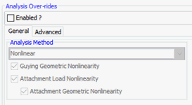
General - Analysis Method
These settings are exactly the same as those at the project level, but these apply to this and only this one structure and are stored in the project file as structure data.
Advanced
Maximum Iteration Count. Sets the Upper Limit for the number of Iterations used during a Nonlinear Analysis to converge on an answer. The Analysis ends when the desired level of accuracy is achieved.

Expert
This tab will only appear if the "Expert" setting is set under Tools->Options->Quick Pole Settings.
This tab has two sub-tabs. The first one deals with the Force Balance equations for the structure. As the Nonlinear Analysis proceeds, the goal is to have the vector sum of all forces at all Segment Nodes to be close to zero. The closer to zero is achieved, the more accurate is the final answer.
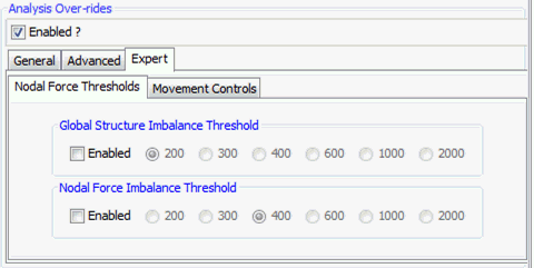
Quick Pole uses an aggregate Global (all Element Nodes above the groundline) value and the worst unbalance Segment Node to help determine whether the Analysis has converged on an answer that is sufficiently accurate.
The second sub-tab addresses the amount of movement that Quick Permits during each iteration of the Nonlinear Analysis process. By restricting movement, the convergence ability of the algorithm is greatly improved.
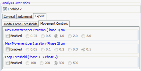
Movement restriction happens in two stages. The included options set the movement limits for both phases, plus the default iterations count when the phase changes.
Guying, Anchoring and Equipment
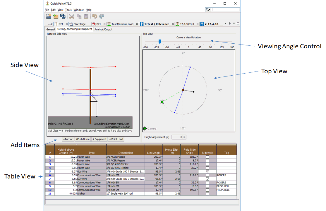
This tab gives you a Top View and a Side 3D View of the pole and all of its attachments. The Camera Rotation Control allows you to see the Side View from different angles and perspectives.
Hovering the mouse cursor over any item in either view will provide additional information about the item in the message panel at the bottom of the Dialog. Some items will also provide a small message box to appear near the mouse cursor with information as well; sometimes called Tool tips.
Top View
The Top View is looking down on the pole from above in a way that matches what you should see on the Work Plan Area. The attachment lines drawn then usually represent several different attachments in different heights that you can only really see in the Side View. So for attachments, hovering information tries to tell you information about everything at that particular angle, such as number and type of attachments, angles involved, etc.
In this View, you can select an end point on Anchors and get information on that anchor. For all other attachments you will need to hover over the attachment segment (not an end point) to get more information about what attachments the line represents. The Top View is also the View that enables you to move anchors. Simply left-click the mouse on the endpoint of the anchor and drag it to a new location and angle. The lead length is updated as you move the anchor and the angle of the anchor is shown in the bottom message box. For your convenience, attachments have their angle and the opposite angle (angle + 180 degrees) in the information they display during hover. If you want an anchor to perfectly support an attachment direction, place it at the same angle as the Angle's Opposite for the attachment.
Side View
The Side View is a perspective that should closely represent pictures you have of the pole or the way you remember it in the field. There are a number of features designed to help you identify which attachment is which. For instance, hovering the mouse cursor over any attachment line will tell you exactly what the attachment is. Hovering over endpoints far away from the pole will tell you information about what it is attached to in the distance, what the span length is and at what attachment height. Hovering over an endpoint on the pole will tell you what height it is attached.
Clicking the left mouse button on a far endpoint of an attachment will select that endpoint and the corresponding endpoint in the Top View. Left-clicking the mouse in the middle of the attachment will select the endpoint on the pole. This enables you to adjust its height of attachment on the pole through either of the two provide height adjustment entry methods. You can enter an exact height value desired in the far right “Set Height” box and hit ENTER, or you can use the “Height Adjustment” spinner control to move this attachment up or down by a certain amount. The control allows you to use its arrow buttons to go up or down by a fixed amount, or you can enter a number in that control and hit ENTER to move a very specific amount.
To improve the ability to move all power wires or communication attachments as a group, you can select several attachments on a pole at once in the Side View and change their attachment height using the "Height Adjustment" spinner control. You can either enter a value to adjust the heights directly and hit enter, or you can use the up/down arrows on the control. This should help in adjusting attachment heights of several items after pole length changes, for instance, or in other situations.
Adding Anchors
To add a default anchor to the scene with a default guy wire, press the +Anchor button. This will add an anchor and guy wire to the scene that you can then adjust. The anchor location is adjusted in the Top View by dragging a left-clicked mouse to the desired location. You can change the anchor type to something different than the default by right-clicking on the anchor node in either the Top View or the Side View.
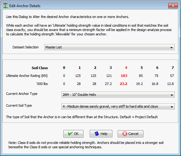
To help you decide which anchor to place, the ratings for the selected anchor are shown in metric and imperial units by Soil Class, with the current Soil Class’s values highlighted in red. You can also adjust the assumed Soil Class around this anchor directly in this Dialog, in addition to changing the desired anchor type.
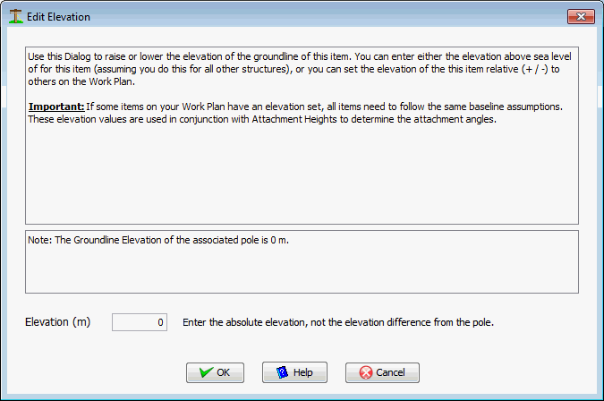
Edit Anchor Rod Elevation
There are times when the anchor rod (where the guy wires attach) is at a much different elevation than the ground-line of the pole. In these cases an elevation value should be entered so that Quick Pole can more accurately compute guy and anchor loads. The value entered is the absolute elevation of the anchor rod measured in the same way as the groundline of the pole.
Changing Guy Wire Attachment Height
You can change the height of attachment of the guy wire on the pole as you would any other attachment height. Simply left-click once on the guy wire in the Side View and use the Height Controls to get the required height.
Changing Guy Wires
You can change the type of guy wire by right-clicking on the guy wire in the Side View and choosing Edit Guying Details. The following Dialog will appear:
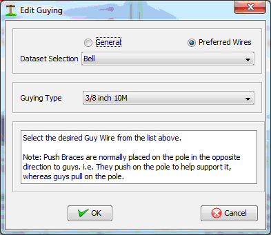
Here you can select from any Preferred wire, or from any of the General wires available in the database. In both cases, wires are grouped by defined Organizations. Simply select your desired wire then press OK.
Adding Guy Wires
To add an additional guy wire to the pole, left-click on the desired anchor location and while holding the left mouse button down, drag it to the approximate position desired on the pole. You should see a line with an arrow moving with the mouse. When you are at the pole end, simply release the mouse button and one default guy wire will be placed from the anchor you chose and the pole. You can then adjust the attachment height on the pole to the exact value you want, or modify the type of guy.
Adding/Editing Sidewalk Fixtures
You can add or change Sidewalk Fixture details by right-clicking on one of the guy wires and selecting “Add/Edit Sidewalk Strut Details”. The following Dialog will appear:
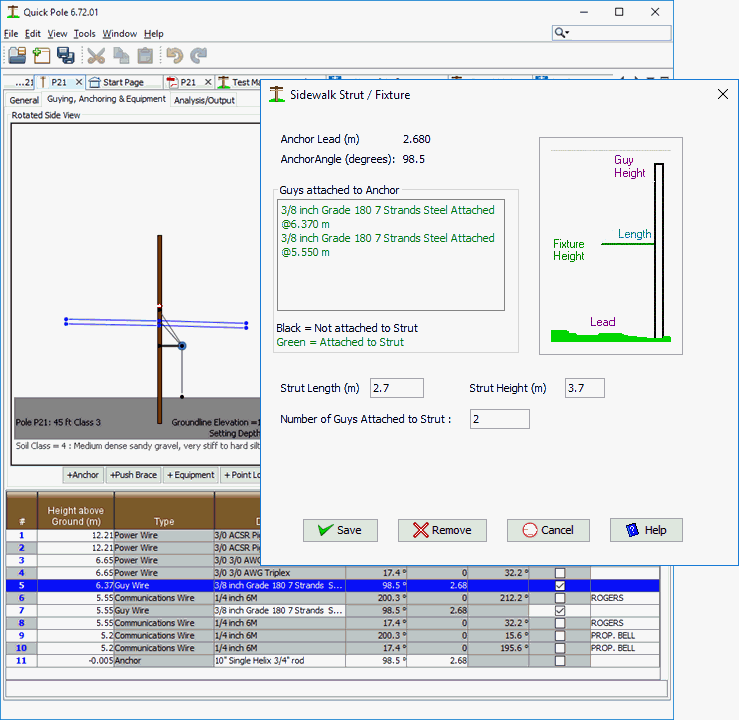
The Sidewalk Strut/Fixture Dialog shows all guy wires on the pole that are attached to the same anchor. By default the strut is always placed at a height of 3.3 meters, but that can be changed. The default for the length of the sidewalk strut defaults to the lead length of the anchor so that the guy wire is vertical above the anchor. You can change this to any length you wish; keeping in mind the common lengths you have available to you. 3.0 meters is quite common and shorter lengths can be cut on-site during construction. As you modify the strut length, the Dialog will keep in sync by updating the color of the guy wire text in the listing box to reflect if it is attached or not. Green means that the strut will push the guy wire out from the pole. Black means it goes past the end of the strut. The “Number of Guys Attached to Strut” value is adjusted accordingly as well. In the special case where a guy wire could be attached to the strut, but in fact goes beside it and straight to the anchor; this can be handled in the Table Edit described later.
In the case where a sidewalk fixture is in place and you want to remove it, press the REMOVE button at the bottom of the Dialog.
Adding Push Braces
To Add a Push Brace to this pole, press the +Push Brace button. This places a Push Brace against the pole in an assumed location. The location of the butt of the Push Brace can be adjusted in a similar manner to anchors in the Top View. Left-click the mouse on the butt of the Push Brace in the Top View and while holding the button down, drag it to the desired location. It is not necessary to specify the length of pole required for the Push Brace as Quick Pole will calculate the length and class required.
Modifying the attachment height of the Push Brace on the pole is similar to any pole attachment. Left-click on the Push Brace in the Side View and use the Height Controls to attach it at the required height.
Adding Equipment
To Add Equipment/Hardware to this pole, press the +Equipment button. This will bring up the following Dialog:
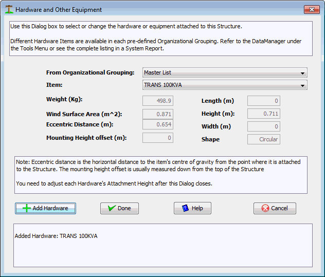
There is a wide range of equipment pre-loaded under different Organizational Groupings for you to choose from. If you want to add something unique, you can add it to the User Grouping via the Data Manager. It will then become available in this Dialog the next time you open the project. This Dialog stays open so that you can add several hardware items at the same time. Use the "Add Hardware" button to add your selected item. Press "Done" when you are finished and they will be added to the structure.
Special Hardware
These Special Items can be found in the Master Database listing only, as they have special purposes and features.
1) Communication Risers attached to the pole
2) Secondary Risers attached to the pole
3) Stand-off brackets with conduit (called Buss Risers in Quick Pole) with three sizes to choose from (12", 24", 36")
4) Primary Bushing locations
The Risers can be added to the pole at their maximum attachment height. The Pole Profile (Side View) will show them from the ground up to this point. Some assumptions for weight have been added to reflect typical usage, including the weight of PVC piping (2" Comm riser holds 3 typical service drops, Secondary Riser holds one 1/0 Triplex). All weight is assumed to be supported at the maximum height. Wind load is computed as one-half of a free-standing pipe to account for partial wind sheltering by the pole.
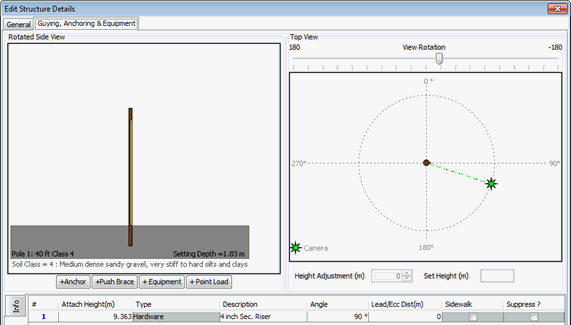
The Riser can be seen as the narrow yellow line in the Side View above.
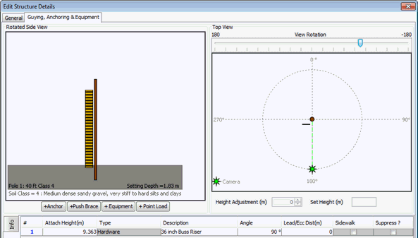
Standoff brackets (we called them Buss Risers) have all of their weight supported by the ground beneath them. Wind load is calculated and divided evenly between their pole support (assumed at the highest point) and the ground. In reality these Buss Risers would be supported at several heights on the pole, however applying the wind load to the highest point will always be a safe assumption. With this assumption it is not necessary to know the exact support configuration of the Buss Riser.
Primary Bushings have been added with two different voltage ranges for clearance purposes; typically used for low hanging transformers. The voltage ranges match the separation requirements of (1.2m and 1.5m) from the NESC & CSA Standards
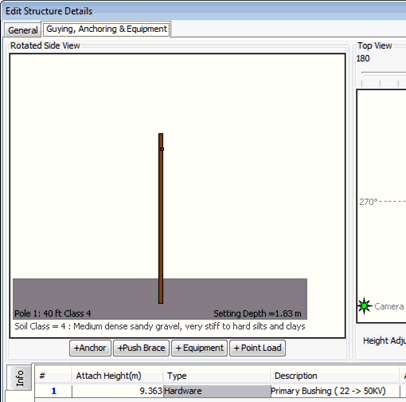
The Primary Bushing locations are difficult to see in the profile view, but easy to see in the Table View and reports.
All of these items, plus street lights, are tested for separation limits to existing hydro and communication line attachments. These results show up in the appropriate reports and instant messages.
Edit/Delete Hardware
To Edit or Delete Hardware, you must first select it in one of the views. Since hardware normally appears very small (since it is drawn to scale), it may be difficult to locate in the Side View and almost impossible in the Top View. If you can right-click successfully on one of the views on the item, the menu presented will allow you to either delete or edit the item. By hovering the mouse over the item, you will be able to tell if a right-click will be successful. The Edit Hardware/Equipment menu item brings up the same Dialog as in Adding Equipment to allow you to select another item.
An alternative means (and usually easier) of selecting the item to delete or edit is with the Table View.
Adding Point Loads
To Add a Point Load, press the +Point Load button. This will bring up the following Dialog:
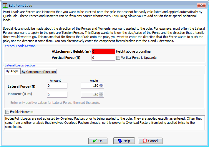
As soon as this Dialog appears, it will highlight the Attachment Height field in red as that is a mandatory field to enter. You can enter Vertical Loads, Lateral Forces and Moments (not common). Since most Vertical Loads are acting as downward (weights) onto a pole, there is a separate Checkbox to the side of that entry in the rare event that you want to use a force that will try to lift the pole out of the ground. Since real vertical loads can only be attached to the side of the pole, the Angle field should be adjusted below to reflect the side of the pole where the vertical load is attached. You can see the impact of this in the "Pole Input Loads" Report as a line item called "Offset Effect". The Top View has the angles shown from 0 to 360 degrees for reference.
Lateral Forces can be entered and are assumed to always place tension onto the pole. If the force is actually a pressure on the pole, add 180 degrees to the angle value.
Moments can also be entered with a separate angle. There is a Checkbox on the right-hand side that needs to be checked in order to enable you to enter values for moments. This is because moments are not common. Enter all moments following the right-hand rule for moments and referring to the Top View for the appropriate angle.
You can enter Lateral Forces in two separate ways:
- Horizontal Force at a specific Angle
- Horizontal Forces broken into their component directions of X and Z.
These different methods are provided for your convenience and will cause the same net effect to be applied to the pole before analysis.
There is a special note about Point Loads in the Dialog that reminds you that these loads will not have Over-Load Factors applied to them like other loads on the pole. This is to help you from inadvertently applying overload factors twice to the same loads if they came from a separate analysis and then combined into this one.
Table View Edits
This Dialog enables you to edit all attachments on this pole in a table format. This has several advantages for doing certain things graphically in the Top View and Side View features.
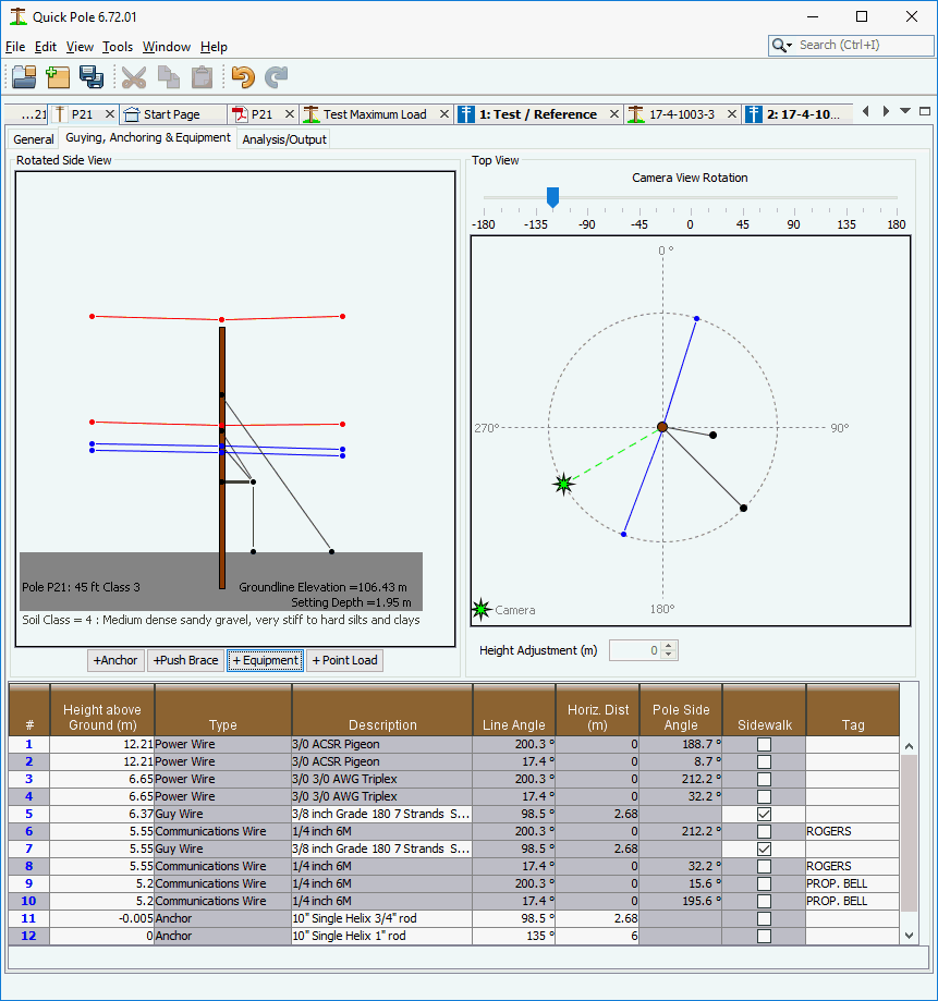
All items that are available for editing have a white background and those that have a grey background are not. Selecting the row number column of any item causes it to be identified in the Top and Side views. You can also delete the item by simply pressing the DEL key on your keyboard. As in the Top and Side Views, deleting an anchor will also remove any attached guy wires.
Selecting the Height above Ground of any item (if enabled) allows you to directly input the exact height value you want. Hit ENTER when done and the views above will be automatically updated.
Selecting the Description field of any row will bring up the Edit Dialog appropriate for that type of item. The exception is any attachment that goes to another structure as those are meant to be edited in the Span Editor Window.
When enabled for an item, the Line Angle and Horiz. Dist fields can also be directly edited. Hit ENTER when done and the views above will be automatically updated.
The Sidewalk Checkbox is displayed so that you can easily see which guy wires may be attached to a Sidewalk Fixture. If you want to keep the guy wire, but remove it from a sidewalk fixture, simply un-check the Sidewalk Fixture Checkbox.
The Tag field is available for all attachments and anchors to help you identify the item. It is usually used to help identify ownership or usage of an item.
Analysis/Output
This tab contains three sub-tabs, allowing you to finalize the design of this structure without having to analyze the entire project. An "Analyze Structure" button is provided so that you can analyze just this structure and see all the corresponding results.
The first tab shows the analysis messages for everything happening at this structure. This is the same set of messages that would be displayed if you selected this structure in Analysis Tree.
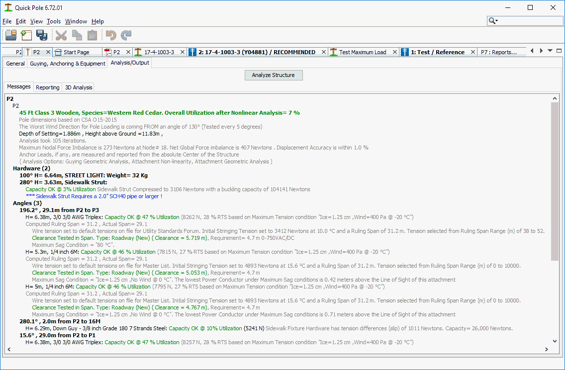
The second tab allows you to create one or more reports on the analysis results for this structure. These reports will open in a separate window with different tabs for each individual report. This window will remain open and available for comparisons with subsequently generated report windows. Quick Pole will also remember your selection of reports from one session and structure to the next. For more details on these reports, refer to the Structure Reporting section.
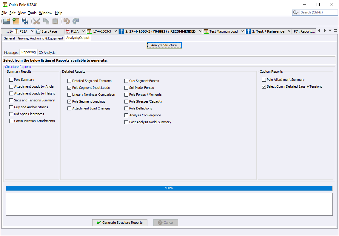
The third tab provides a 3D view into the structure model and the resulting analysis results. The first option shown is typically the structural model.
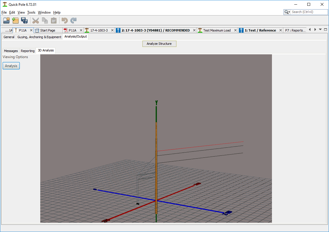
By pressing the Analysis button, you can change the view to show the Analysis view. Pressing the button again reverts the view back to the model, similar to a toggle type button.

Overloaded components and sections of the pole will show in red (guys, struts, anchors, pole segments). Moving the mouse so that the center of the mouse arrow hovers over a component will provide a popup message box about its analysis results. The pole is broken into several pole segments for analysis purposes, which you can see by the different colors along the pole. Green is lightly loaded, yellow is moderate and red is overloaded.
Using the left mouse button you can rotate the view easily (horizontally or vertically) by placing the mouse at a certain point and dragging the mouse. Zoom control is via the center mouse wheel. Panning of the view is available by pressing the mouse wheel down and dragging the mouse to another location.
Created with the Personal Edition of HelpNDoc: Full-featured Documentation generator