Edit Attachments
This tab of this window is dedicated to modifying attachments in the span.
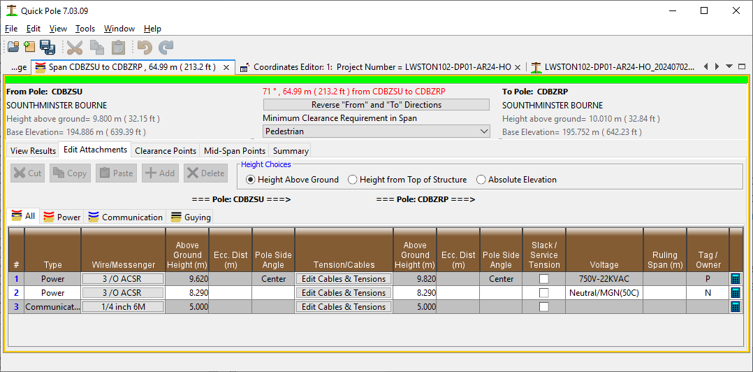
This tab is itself broken into various categories of attachments, plus one tab that contains all attachments. There is no need to implement your changes on a particular tab, other than the Add button will add the your default attachment for the particular tab open at the time. The Add button's default values can be changed in User Preferences (Tools->Options). All tabs keep in perfect sync with each other.
At the top of the window is some relevant information about both ends of the span; location name, structure height above ground and base elevation. You can flip the span directions (From/To) with the "Reverse From and To Directions" button. This is useful sometimes when you are looking at plans, field data or photos with a different perspective than presented in Quick Pole.
Also near the top is a button to select the default clearance type for the span. This value is not mandatory, but if set will be used to determine if clearance standards are violated anywhere within the span. This can be used with or without setting specific points within the span with different clearance requirements. It is typical to use the least demanding clearance requirement for the span and then set specific points in the span for more demanding requirements. For example, you could use this button setting the span default is pedestrian, but then include driveway and road locations on the Edit Clearance Points tab. If you have two or more clearance points in the span with the same clearance requirement, Quick Pole will extend that requirement between those two points. This can be seen if you show the clearance requirements line in the Span Profile. A very common scenario would be to mark a span for pedestrian clearance requirement, but then have roadway clearance requirements on both sides/shoulders of the roadway.
A DELETE button will be enabled is there is at least one row selected in one of the tables. To delete an item, select it by clicking on a row and then hitting the delete button. It is often best to click on the row number in the left-most column as some columns offer choices if you click on them. You can select additional rows by holding down the CTRL key and left-clicking the mouse on additional rows. You can also hold the SHIFT key down to select a whole range of attachments. Once multiple rows are selected, you can use the DELETE key to delete all of them at once. Once the appropriate rows are selected, you can alternatively use the Delete Key on the keyboard instead of clicking the Delete button.
Cut, Copy and Paste
Quick Pole has an internal private clipboard to enable Cut, Copy & Paste operations on Span Attachments. This can be used to duplicate similar attachments or groups of attachments across pole spans or within the Table Editors.
By clicking on the very start of a row, that attachment becomes eligible to be Copied or Cut from the table. Using the same selection rules above mentioned for the Delete button, you can Cut or Copy the selected rows. This places a copy of these selected attachments on Quick Pole's internal clipboard. They are then available to be pasted to other spans, in addition to the currently selected one. For instance, Copy or Cut rows in the selected span, select a new span in the Work Plan View and then you can use the Paste button in this window or right-click on the span in the Work Plan View and select the Paste function. You can also copy all or a category of attachments via Work Plan Area functions and they will then be available for pasting in the Span Editor/Viewer Window.
For Pasting actions:
In most cases the attachment heights will be modified to follow the same distance from the top of the structure as before, and likewise eccentric attachment angles will be adjusted to best reflect the previous desired relationship to the main line; if the attachments are offset from the side of the structure (eccentric distance >0). After pasting the attachments, you should check the heights of all attachments against your field notes. In many cases they will be very close and this method will save you a good deal of effort.
A copy is also placed in your computer's (System) clipboard and can be pasted into Excel or similar programs. Some fields are complex objects and will not display properly in other programs (blank), so this may be of limited value in some programs.
Field Edits
Wire/Messenger:
Clicking on this field allows you to change the Wire for this attachment. It brings up the following Dialog:
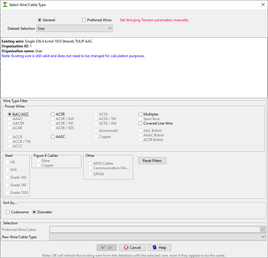
- The default way of selecting a Wire/Messenger is to select one of the Preferred Wires defined for a particular Organizational Grouping. The reason for this is that the tension parameters are already defined for these wires. You can also select one from the General listing, which puts a reminder in this Dialog that you also need to define the tension parameters manually. Otherwise this wire will not be tensioned properly.
- In this Dialog you can use the Radio Buttons in the middle section to narrow down the choices available in the Wire/Cable listing. The buttons are disabled if that type of wire is not available in the selected Organizational Grouping. For convenience, the Wire/Cable listing can also be sorted by either Codename or Diameter. When done selecting the one you want, press the OK button.
Height:
This field respects the "Height Choice" selection of radio buttons above the table. This means that all height values can be set as
- Height above ground
- Height from top of structure
- Absolute elevation
This field appears in two locations, for the "From" and "To" structures.
Ecc Dist:
This is the distance (if any) that the attachment is held out from the side of the pole. Also called Eccentric Distance. This is common for certain attachment brackets or if the wire is on a crossarm. If a value is placed here, the Pole Side field is also required to have a value. Do not try to estimate the distance to the absolute center of the pole as Quick Pole calculates that automatically and adds it to the Eccentric Distance entered here to calculate loads. Only the distance from the face of the pole is required.
Pole Side Angle:
In this field you are being asked where exactly is the attachment attached to the pole. Thinking about how the pole is situated on the Work Plan View and recognizing that 0 degrees (True North) is up, select which angle best represents the attachment point on the pole. In the case where the attachment is above the top of the pole, this would mean the direction it came from.
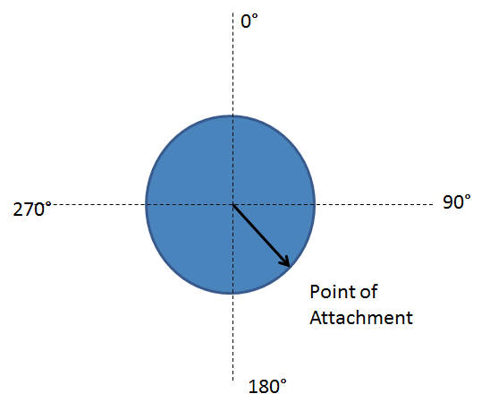
A few standard choices are provided that cover the majority of cases.
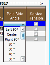
Left and Right would be as viewed from the "From" pole, to ensure consistency. All values entered, including Left, Right and Center, will not automatically adjust if the pole is later moved. If you move the pole, you should re-check your entries here. The Left, Right and Center convenience selections are converted to actual angle measurements before being stored. For this reason, it is always recommended to correct/fix your pole locations before adding attachments.
If an eccentric distance is entered, this same angle will be used.
Edit Cables & Tensions:
Selecting this column for an attachment will bring up a Tension Adjustment Dialog. Refer to the Tension Adjustment section below for more details
Slack/Service Tensions:
Check this box to force the wire tension to tensions pre-defined for Service Wire or slack purposes. These values would come from the Organizational settings for this particular wire. This is always used to indicate that the tensions expected here would be lower than pole to pole mainline tensions and more like service tensions to buildings/houses.
Voltage:
Specific to Power wires, the voltage of the wire can be set to values that can be found in clearance and separation tables of the standard (CSA/NESC) that you are using with this project. There are two special ones added specifically to Neutral wires which you may want to use. Some standards have special rules and abilities, so you want to identify them as different than just a power wire with voltage less than 750 volts. One selection is just for a Neutral wire and the other is for a Neutral wire that you believe should only have a thermal limit of 50C.
Ruling Span
Quick Pole uses the span length to estimate the proper Ruling Span distance to use for Sag & Tension purposes. See "Understanding Ruling Spans" for more details. There are times when extra poles are installed into the line for customer purposes that make the actual span lengths much different (shorter) than the actual Ruling Span length; which was used to tension the line initially. In these rare cases, you can use this column to over-ride the Ruling Span assumption so that the appropriate Ruling Span tension is applied to the span.
Tag
It is often helpful for Attachments to use this field to identify the Owner of the attachment. This field can be used for anything though and will be presented in other windows and reports as an additional identifier that you may find helpful.
Calculator
This launches a copy of the attachment in the row into the Sags & Tensions Calculator. There it is possible to explore this attachment's calculations in more detail. To do this, the attachment is copied exactly onto a different set of model poles that take into account the current attachment heights and the base elevations of the existing poles. This creates the attachment to model as a "Selected Span". A "Ruling Span" attachment is copied from this and modeled with equal elevation at both ends of the attachment. For both the "Ruling Span" and the "Selected Span", if the average attachment height of the original attachment is greater than 10 meters, the appropriate height factor adjustment is included in the load calculations, for specific load cases (like Extreme Wind), as required by National codes. This is only possible when launching the Sags & Tensions Calculator from the Span Editor, and will be removed if the elevations are changed in the Calculator itself. The angle of wind approach is always 90 degrees. Unlike in a structural analysis, there is no effectiveness factor computed based on the angle of the wind and the span.
Tension Adjustment and Cables
The same Dialog comes up for Power and Communication Wires to Edit Tensions or add cables.
Tension tab
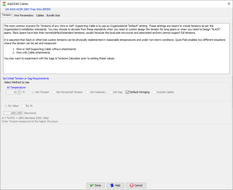
This tab allows for custom adjustment of the wire's initial stringing tension or sag condition. If the wire's configuration contains multiple wires, a reminder message will appear noting that tension values should be the total tension from all wires. The “Default Stringing Tensions” checkbox is checked by default to force the use of Organizational settings to define the tension in this attachment.
Defaults:
The default stringing tension used by Quick Pole is determined by several factors. The most important factor is whether the wire has been sourced from a Dataset as a "Preferred Wire". If so, the wire's tension will be determined by its ruling span length and status as either a Service Wire or a wire under Slack Tensions. The Service Wire status will apply if the span length is less than 38 meters and either it is used in a span to a building or the Service Wire/Slack tension checkbox has been set in the Span Attachments Editor for this wire. If the wire is a "General Wire" as opposed to Preferred, the Service Wire/Slack tension checkbox will generally force a stringing tension of 300 Newtons. Otherwise the type of wire, and in some cases whether it is run pole to pole, will determine the default stringing tension. The rules are as follows:
- Steel or Figure 8 wires follow tension defaults that largely align with communication companies.
- Communication service wires default at 60lbs pole-pole and 30lbs otherwise. This is standard industry practice.
- ADSS – 1% sag
- Else all aluminum wires are set to 10% RTS, otherwise 15% RTS, in accordance with recommendations from IEEE 524
Wire tensions are compared against lower limit requirements to support at least its self-weight in the span. So there could be some adjustment by Quick Pole from what you have entered.
If the Service Wire status applies and the Project Settings have the "Adjust Service Wire tensions based on Study" checkbox selected, the wire tensions will be adjusted to achieve 0.4m of vertical sag. If this value is more than that set under Preferred Wires settings, the value is limited to that. Most often this study requirement will reduces the stringing tensions to a more realistic value, creating more realistic loads on the attached poles.
Un-checking the “Default Stringing Tensions” checkbox enables a number of different options for defining the tension. All of these options involve an Unloaded condition; no wind or ice loading. Through the appropriate option, you will be selecting a real condition that could exist in the field, or a new proposed condition that could be measured and set in the field by installation forces. Quick Pole will use this real measurable condition to calculate the appropriate Sags and Tensions and related loads.
In the appropriate situation, such as with Communication Messengers, the tension situation can be defined to “Include Cables” via that Checkbox. This is ideal for existing field conditions where additional cables are lashed (attached) to the support wire/messenger today and you want or need to re-tension, or set a specific tension. It works with all tension setting options.
Non-default Options:
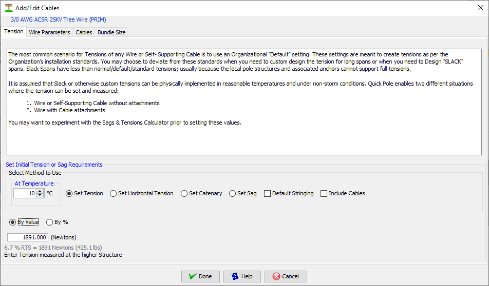
1. Set Stringing Tension
This is the most common option for attachments as it is easy to measure and set the exact tension at a specific temperature in the field with a dynometer. You can enter a tension amount as a percentage of the breaking strength of the wire/cable or enter a specific value in either imperial (pounds) or metric (Newtons) units.
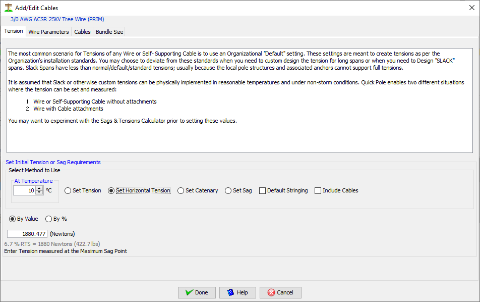
2. By Horizontal Tension
This option is not very common, but possible. You can measure this value at the maximum sag point of any wire.
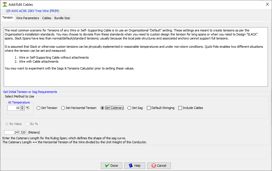
3. By Catenary
This option is most common for Power Conductors when aeolian vibration is of particular concern. The catenary value is a ratio that can be the same for a wide range of wires, while still resulting in different tension amounts. Some guidance for appropriate catenary values can be found in various standards, from the manufacturer or from local experience.
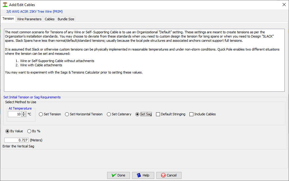
4. Set Sag Amount
This is very common for modeling of existing conditions you may find in the field. If the wire/cable is already in place, you can get Quick Pole to use this existing tension to determine all other Sags & Tension conditions. The value entered for Sag should be measured at the maximum sag point and is the difference between that height and the lowest attachment height (if one of the attachment heights is lower than the other in absolute elevation terms). This would be the same as the VSag amount in detailed reports.
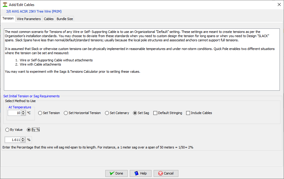
5. Set % Sag
This option is very common for Self Supporting Cables with non-metallic central strength members (ex. Kevlar yarns). The results of this setting would be the same as the "Set Sag amount" feature above, where the amount=% * span length. This sag amount is a "vertical sag" Vsag found in detailed reports.
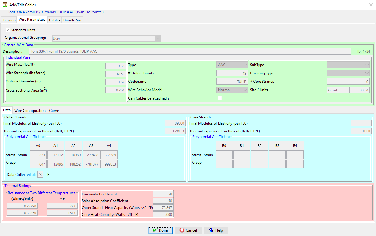
Wire Parameters
This tab is the same as found in the Sags and Tensions tool, but is repeated here as it can be very useful to confirm that you have the correct wire selected.
The first sub-tab shows basic information.
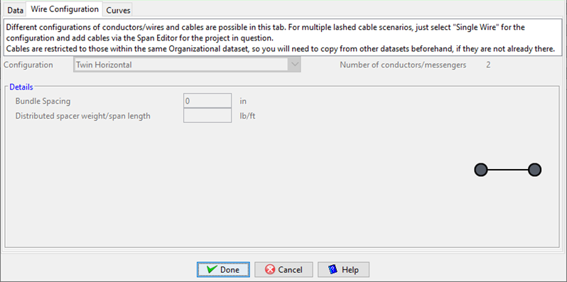
The second sub-tab provides a read-only view into the wire's configuration details.
The third sub-tab shows a pictorial view of the wire's nonlinear polynomials.
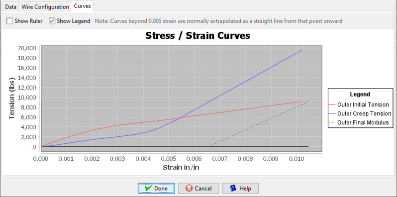
Cables:
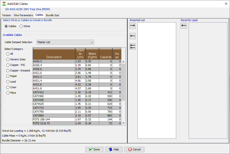
This Dialog can be used to attach cable or wires to wires. The assumption is that they are bundled together with lashing wire or they are field-wrapped around the wire.
At start this Dialog defaults to show the “default” Dataset listing of communication cables that you set in your defaults. By choosing a different Organizational Dataset, other cables may be available. When first displayed, the category filter is set to “All” so that you can see all communication cables. Several different category selections are available so that you can filter the list for the type you are trying to find.
If you select "wires" to be added to this wire, a different view appears:
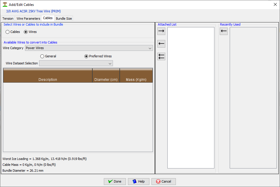
Instead of Category selections with radio buttons, there is a drop-down category field that permits "Power Wires,Messengers,Guy Wires,Self-supporting wires,Comm service wires,other comm wires, all wires". Like the cable selection option, you would also need to select a dataset to choose items from.
The table heading in the list that is displayed allows you to sort the list by left-clicking once or twice by the column desired.
When you find the cable/wire you want in the table listing, double-click the corresponding row to place it in the attached cable listing on the right-hand side. Alternatively you can click the row once to select the cable/wire and use the Right Arrow button to copy it to the list. The cable/wire attached listing works in a similar way in that you can select the item and press the Left Arrow button to remove it from the list. The Double Left Arrow button removes all items from the attached cable/wire list. As items are added or removed, you are presented with calculated results for Bundle Diameter, Cable Mass and Ice Loading in Imperial and Metric units. These are located under the table in the center of the Dialog.
Bundle Size:
Although this is most often used for communication wire purposes, this can be useful for bundled or unbundled power wires as well. It shows you the calculated bundle size and allows you to over-ride this value with your own estimate; if desired.
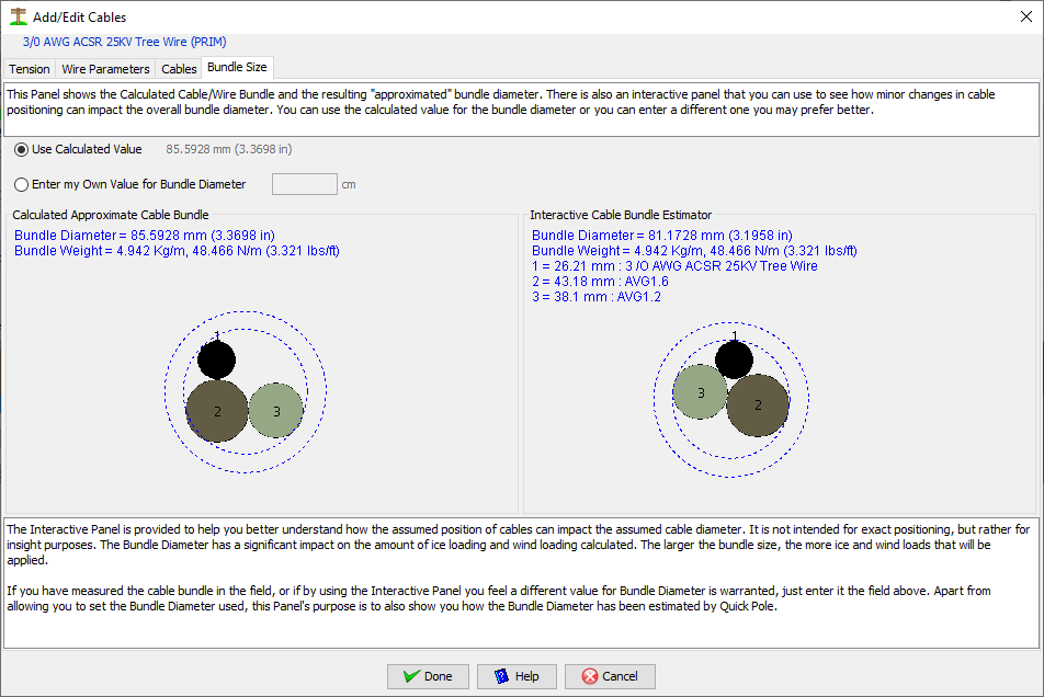
The inner dashed circle represents the approximation of the cable/wire bundle size. The Outer dashed circle represents the extent that the Ice (from the deterministic weather load case) will build up on the estimated bundle size. The resultant Outer circle is the estimated size that Wind Pressure will push against. The area between the two dashed circles represents the amount of frozen precipitation that is estimated to attach to the bundle. It is recognized that the ice amount will never form into a perfect circle and may leave air gaps (voids) beneath it. However this estimation is considered valid by many assuming that this volume of ice will form closely around the actual bundle.
If you have reason to believe that the bundle size is different than the size calculated, select the Radiobutton to enter your own value and enter it in the field provided.
The bundle diagram on the right is interactive and allows you to use the mouse and drag cables to a different location within the bundle. As the cables move within the bundle, the overall bundle size will be calculated and will likely be close in value to the automated version on the left. Use this interactive model to determine if there is a better estimate of bundle size than the automated one.