Guyed Point Load Response
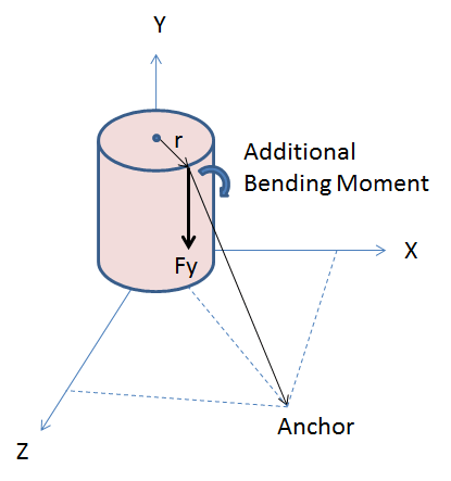
This test is designed to assess the impacts of guy attachments on a pole to support the required loads. Since the guy is attached at the side of the pole and not the center, additional bending moments are created; which in turn can impact how multiple guy attachments share the load. Standard guy hardware typically adds an additional 0.020m of offset, which should also be considered.
The focus of these tests are to ensure that the combined models of both the pole and the guying components work together in a consistent way to provide an accurate overall response. Individually the models may behave as expected, but when combined, additional consistency constraints are demanded in order for them to work together properly.
The Point Load tests are repeated here with the following guy options:
- Guy wires are attached appropriately to support the load (proper angle) for one test.
- For the single Point Load tests, repeat those tests with the guy angle changed to be at an additional 30 degrees clockwise. This verifies torsion is considered in model as the guy will not be located to directly support the load.
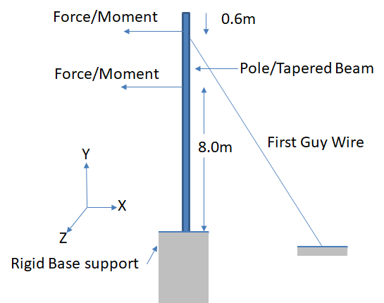
- One guy shall be placed 0.15m below the top load for first test. A second test shall add a guy 0.15m below the second load (when present).
- One Anchor shall be at 3.0m lead when measured from the face of the pole. (i.e.not from pole center)
- Repeat all tests above with a sidewalk strut at a height of 3.3m and length of 3.0m
- Reporter should identify if guy wire modulus was considered fixed or if the nonlinear parameters were taken into account.
Only a Linear Analysis is required for this test.
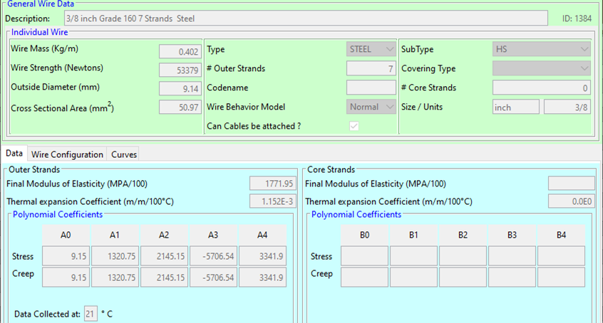
The guy wire to be used is:
Sidewalk strut is a 2" schedule 40 pipe.