Structure Framing
Quick Pole can use Framing Standards within an Organization to help populate several poles at once with Power wires, support hardware such as crossarms, neutral wires and secondary wires.
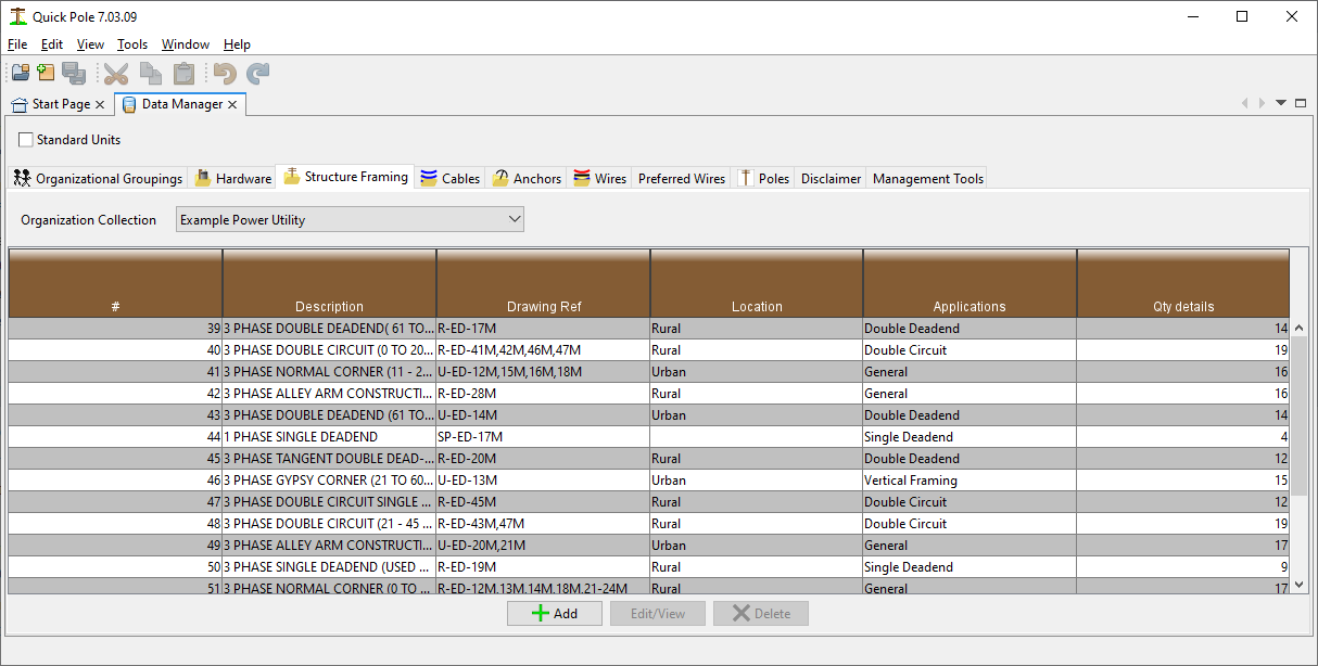
The listing shows the different Framing Standards available for use in Quick Pole, drawing reference numbers, application and the number of framing details associated with the standard.
The Report button will create a Report on all Framing Standards within the Organizational Grouping being displayed.
If you are in an Organizational Grouping that you don't have permission to change, there will be a "View" button enabled at the bottom of the Window. Alternatively there would be an "Edit" button, and the Add button would be enabled. View, Edit and Add buttons display a Dialog with the same fields as follows:
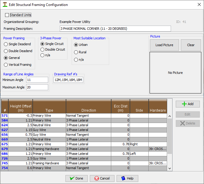
Framing Description
Enter the name of this Framing Standard that would make sense to you or your users.
Most Suitable Location
This value is related to the different span lengths used for Preferred wires in an Organization. Urban areas would normally use Framing Standards that support either Urban or Rural span lengths. Rural areas should not normally use Urban Framing Standards as they may not be strong enough. Select from Urban, Rural or not applicable.
3 Phase Power
If the framing is for 3 phase, you can select that it contains one or two 3 phase circuits. Single phase framing would be n/a.
Power framing
This is primarily for sorting purposes, but also to help you find the framing standard you want.
Range of Angles
Enter the applicable line angle for this type of construction. If this is for a tangent pole line only, enter 0 for both entries. Otherwise define the minimum and maximum intended line angles.
Drawing References
Enter here the applicable standard references within your Organization. Note that Quick Pole Framing can address a few different applications using the same basic definition.
Picture
Enter here a drawing or photo of what this Framing Standard looks like.
Table of Items
This table contains all the detailed separate items associated with this Framing Standard. It includes the items required to frame the basic pole, plus it should include how single and 3 phase laterals should be addressed when they come off this pole. In addition, all preferred guying locations should be indicated at the same time for the basic pole (on a corner) and the laterals.
Each individual Framing Item can be viewed, edited or added depending on your permissions. The fields are described as follows:
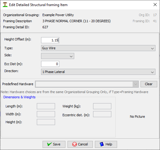
Height Offset
Enter the distance from the top of the pole downward.
Type
Select from Primary Wire, Neutral Wire, Secondary Wire, Guy Wire, Framing Hardware or Other
Side
Enter the side of the pole when viewed facing the next pole in the line
Ecc Dist
If the item is held to the side of the pole (on a crossarm for example), enter that distance here.
Direction
This is really how different applications get applied to the same pole. Normal Tangent includes corner poles, 1 phase lateral, 3 phase lateral, Inline Deadend T (for towards next pole), Inline Deadend A (away from next pole) are the choices.
Predefined Hardware
If the line item is for Hardware, choose an item from the drop-down list. Only hardware already defined in the same Organizational Grouping is available.
Dimensions, Weights and Picture
If a Hardware item is chosen, all of these items are displayed from values in the database.