Hardware
The Hardware Window Tab is used for all hardware and equipment items you may want to attach to a pole. Any item under any Organizational Grouping is available to use in your projects. There are no restrictions related to Pole Owner or otherwise.
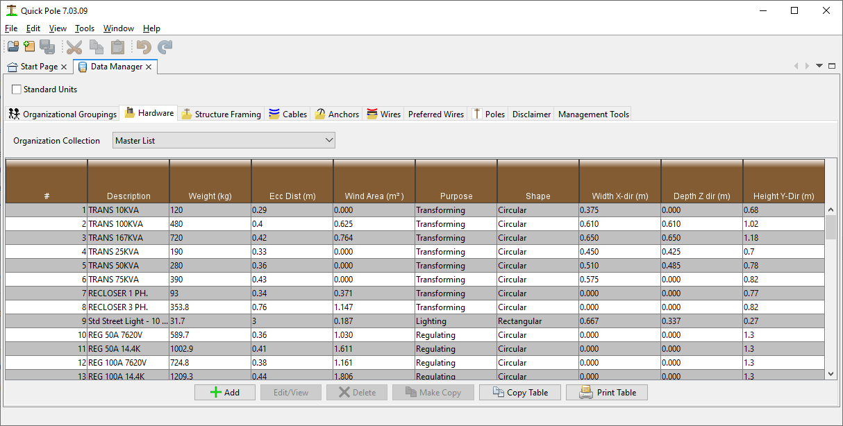
The table listing will change for each Organizational Grouping you select from the Drop-Down list of choices at the top of the tab. By pressing the "Report" button you can generate a report you can print or export to PDF or Excel (for example) on all the Hardware items stored in the database; within this Organizational Grouping only. Only a subset of information is shown in the listing. You can scroll through the list and select the item you want more information about or want to Edit. If the item is managed by Sonideft, you will only be able to View the information. The "Make-Copy" button is useful to copy an item from the current dataset into another; perhaps with some slight changes.
The data attributes are defined as follows:
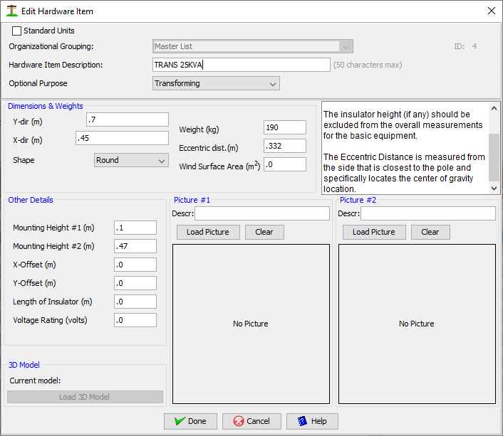
Hardware Item Description
Enter whatever description you feel best describes the item.
Purpose:
Selectable values are Structural, Regulating, Transforming, Lighting. This is handy for sorting the hardware listing as the table column heading will sort the list for you if you click in them.
Dimensions and weights:
Hardware items are measured and stored as if they are positioned on the X-axis as shown below. Either the bottom of the hardware will be resting on the X-axis, or its mounting hardware. In specific projects you will be able to change their actual height and angle of attachment. Prior to editing any of the hardware's attributes, select the most appropriate "Purpose" from the drop-down choices.
The length, width and height basic dimensions of the item are fairly self explanatory. Enter these while also selecting the item's "Shape". The Eccentric distance is the distance to this item's center of gravity from the side of the pole to which it is mounted. In the case of items extended on long brackets that are not perfectly horizontal, you may also have a similar measurement called "Y offset" to enter. This tells Quick Pole the height of center of the equipment at the end of the long bracket. This value is used for both wind and center of gravity purposes.
Most pieces of equipment will have at least two locations that are used to secure the equipment's mounting bracket to the pole. Enter the vertical height above the bottom of the equipment or of the mounting bracket for each mounting position. The top mounting position is assumed to carry all the required loads onto the pole. This is not always true, but is on the safe side of assumptions for pole loading calculations.
Some equipment will utilize stand-off brackets or other similar methods of installing the equipment away from the pole. This is called the "X-Offset" and is measured between the face of the pole and the side/edge of the equipment.


Insulators can have a stand-off bracket with a specific X and Y offset, plus an angle measured from the horizontal. This is typical of side-mounted insulators. The insulator itself would have a defined length, diameter and voltage rating. The voltage rating is for phase to ground voltage values, not phase to phase which are about 1.8 times phase to ground values. For convenience, the data for the stand-off bracket (if present) is entered with the insulator data so that it can be applied to projects as one unit. Since different mounting options are possible, the eccentric distance is entered for the insulator only and does not include the mounting bracket effects.
3D Model
Use this feature if you have a 3D model of the hardware item to use for visualization.
Pictures
You can load up to two pictures for each hardware item, with description. Possibly from different angles.