Wires
Wires in Quick Pole represent virtually anything that can be strung between two poles or between poles and a building. They can all support their own weight and some of them can support the weight of Cables and mid-span items as well. There is a wide assortment of wires stored in the Master Organization collection of many different types. If you go to the Select Wire/Cable Type Dialog for any wire attachment between poles, you will see all of the different wire categories available in the database. At time of writing, there were 22 Power wire categories (including aluminum, copper, steel core, multiplex and Spun Buss varieties), four (4) steel wire rope categories, two(2) Figure 8 categories, Optical Guy Wire (OPGW), All Dielectric Self-Supporting (ADSS)Cables and Communication Wires. Over 1400 individual wires on file and maintained by Sonideft.
In addition to the database storing the basic wire data you would expect, it also contains the Modulus of Elasticity and creep polynomials for up to two separate strength components in each wire. This way the full non-linear characteristics of the wire can be modeled for accurate Sag and Tension calculations.
Some wires are strung with cables attached either through the use of spacers of from the wire used as a messenger, or by plastic extruded over both the wire and cable so they become one unit. These cables are termed "composite" cables and include as examples: Figure 8 cables and Hendrix aerial spacer cable systems.
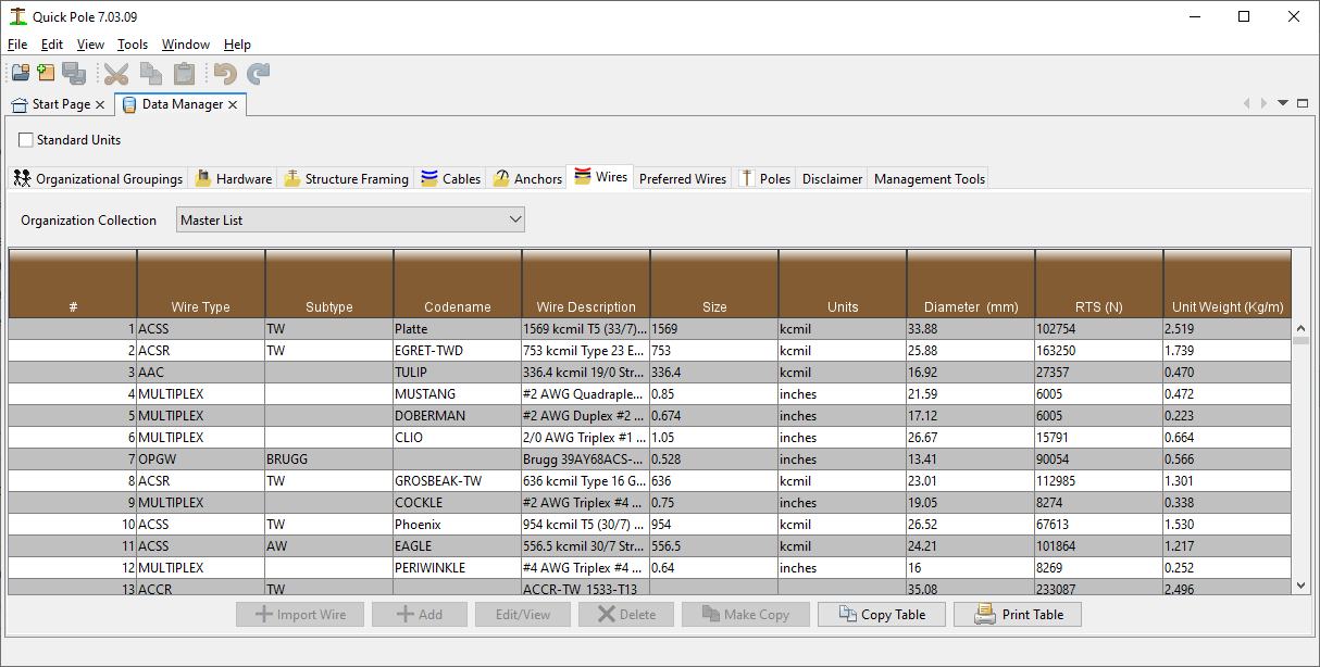
The Report button at the bottom of the Window produces a Report containing all wires within the Organizational Grouping shown, sorted by Wire Type. The report will be created and shown within the System Reports Window Tab.
The Import button enables you to add one or more wires into the database.
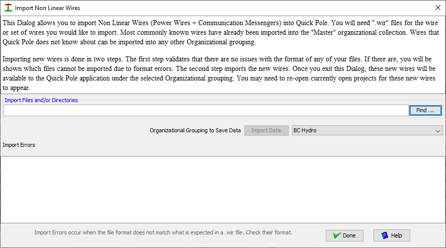
To use this Import feature, you must have the wire data available in .wir file format. This is the same format that most manufacturers provide so that the wire can be imported into PLS-CADD.
Step 1 is to use the Find button to find the file or directory of files.
Step 2 is to select the Organizational Grouping you would like the wires to be imported into.
Step 3 is to push the "Import Data" button. The large message box will show you the progress and any errors it encounters. If there are any errors in the format or contents of the .wir file, the wire it had an error with will be in the message box. Be sure to scroll through these messages to find any errors. If an error is found you have the options of:
- Editing the .wir file directly to correct errors
- Request a new .wir file from the manufacturer
- Add the Wire manually, using the existing .wir file as a guide to the values. This option is the least desirable as it is prone to input errors. If this option is chosen, compare a successfully input .wir file with the one you have and its inputted data.
Step 4. It is very important to ensure that the "Type" and "SubType" fields have been detected properly. If these are empty or do not match others in the Master Database, they will not be available for use in your projects. The spelling must be exact. Uppercase is preferred, but not mandatory. As an example, ADSS cables will never have these fields populated as part of the import. Type and Subtype are fields that Sonideft has included into the Quick Pole database which are not part of the .wir file format; although many (not all) are interpreted for you.
The "Make Copy" button at the bottom of the screen allows you to select a wire in the table listing and make a copy of it with modified parameters (name, diameter, etc) and to restore it in the same Organizational Grouping. The functionality is very similar to use of the Add or Edit buttons, except that the input data to start editing comes from another wire.
General Data
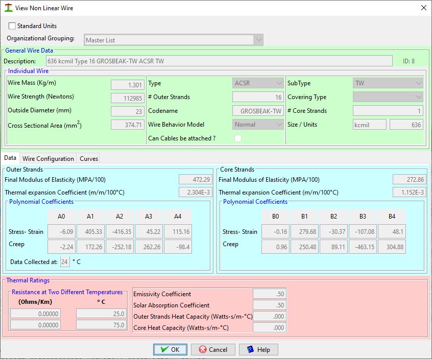
The first "Data" tab in this Dialog contains all the detail data required for the "wire" component only, as follows:
English Units
Select this Checkbox to enter/edit all these values in English or Metric Units.
Description
Enter any description you think is appropriate to find this wire.
Wire Mass
This is the weight of the wire per unit length.
Wire Strength
Rated Tensile strength of the entire wire
Outside Diameter
The overall diameter of the outside of the wire
Cross sectional area
This is the total cross sectional area of all strength components of the wire. For example, for ACSR wires you would add the cross sectional areas of both the steel and aluminum components to enter her.
Type
Enter one of the Wire Type categories discussed earlier
Codename
Enter a codename, nickname or any other short familiar phrase normally associated with this wire. This entry can be empty
# Outer Strands
The number of individual strands on the outside of the wire
Wire Behavior Model
Most wires would use the "Normal" option, but "GAP" is also available for wires with two strength components of different characteristics. GAP wires are designed so that there is minimal friction between the inner core and the outer wires. This enables both to expand and contract independently. Also, when the wire is initially strung, all tension is applied to the steel core alone. The end result is a wire that has less sag at high temperatures because the sag becomes dependent on the thermal characteristics of the steel core alone; which expands less than aluminum. Use of this attribute is NOT currently implemented in Quick Pole. If you have a need, please let us know.
SubType
For greater clarity, some Wire Types have sub-categories. Enter the subtype, if applicable
Covering Type
The choices are none, POLY or XLP. None would represent a bare wire, POLY or XLP would be for a plastic covered wire
# Core strands
The number of individual wires in the core of the wire.
Size/Units
Mainly for sorting purposes, enter the size amount and the units of the size.
Outer and Inner Strands
Enter this section as per manufacturer's instructions. If there is only one type of metal in the wire, enter this information in the OUTER wire section.
Thermal Ratings
Enter this section as per manufacturer's instructions.
Wire Configuration
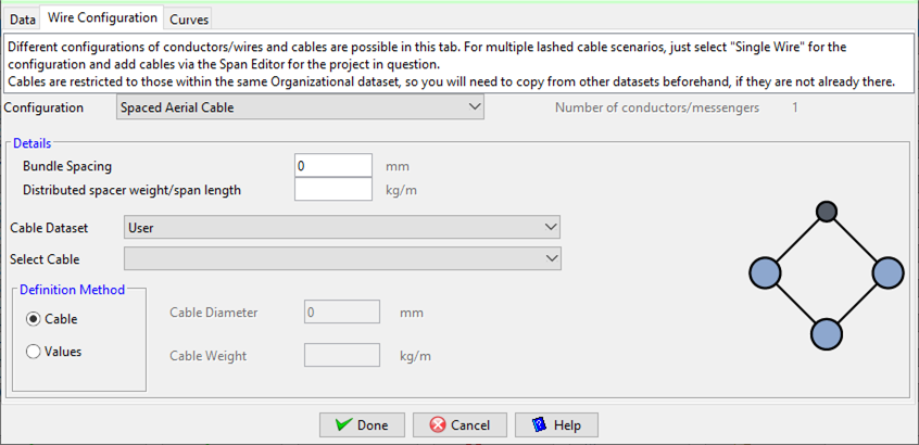
Quick Pole supports several different wire configurations to meet almost any need in a Distribution Line. It should be noted that wires with a special configuration should be configured in the Data Manager as this ability is not available while editing a project.
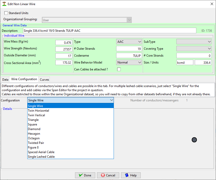
The following wire configurations are supported:
1) Single wire. This is the most common scenario where you want to attach one wire. Lashing or spiral wrapping cables is usually an option.
2) 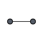 Two horizontal conductors separated with a spacer.
3) 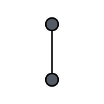 Two Vertical conductors separated with a spacer.
4) 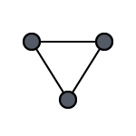 Three conductors in a Triangle configuration, separated with spacers.
5) 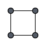 Four conductors in a Square configuration, separated with spacers.
6) 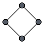 Four conductors in a Diamond configuration, separated with spacers.
7)  Six conductors in a Hexagon configuration, separated with spacers.
8) 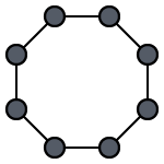 Eight conductors in a Square configuration, separated with spacers.
9) 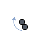 Two conductors twisted amongst themselves.
10) 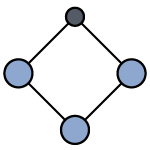 Spaced Aerial Cable Systems (one messenger, three spaced cables).
11)  Figure 8 wire/cables. The messenger/strand is mechanically bonded to a communications cable.
12) 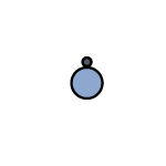 Single wire/messenger/strand with one integrated cable. The cable can be lashed or spiral-wrapped.
Depending on the wire configuration chosen, extra data is required or optional.
Bundle spacing refers to the spacing between the wires or cables.
The distributed spacer weight per span length can be used for a few different purposes. For wire configurations that employ a spacer, determine its weight and how many you deploy in a typical span. Take the weight of all spacers in a typical span and divide by the typical span length. This allows sags and tensions to be calculated. You can also use the distributed spacer weight to deal with most scenarios that use aerial marker balls, using the same technique.
The cable options apply to scenarios where one or more cables are used in the wire configuration. You can select a cable from any organizational dataset you have on your computer. Alternatively you can enter just the diameter and weight.
Curves
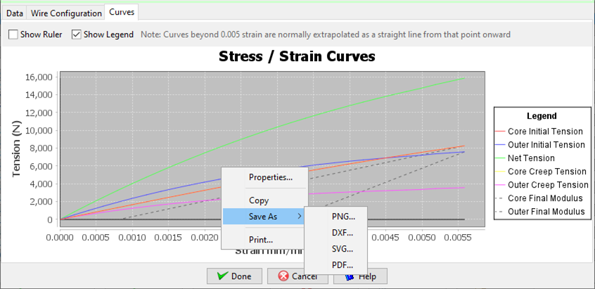
This tab shows a graphical view of the nonlinear polynomials for the outer and core(if present) materials in the wire. It should be noted that many polynomials provided by manufacturers create curves that do not go through the (0,0) location, which is essential before they are used. Quick Pole employs an industry recognized methodology to shift these curves, if required.
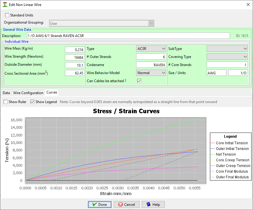
In this chart, the dashed lines represent the outer and core (if present) Final Modulus of Elasticity lines being applied to the curves at the end of the 60% of the Rated Tensile Strength of the wire. The distance from where this line intersects the zero tension line and (0,0) is the amount of permanent/plastic stretch/creep that will occur in the outer/core components. Since real projects are unlikely to tension wires to this limit (100% utilization = 60% RTS), all Sag & Tension calculations need to be individually performed in each span; as the loads and permanent stretch will be different.
The Show Ruler Checkbox allows you to investigate these curves at specific points of Interest.
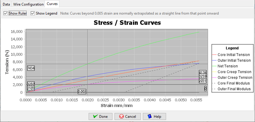
As with most graphs in Quick Pole, a right-click menu option is available to store the graph in many formats.
