Single Wire Sags & Tensions
The tension of attached wires to structures are the major loads the structures are required to support, under a variety of load cases. As such, any deviation from expected norms for tensions will have a significant effect on calculated single and multi-structure analysis results. Their resulting sags under various load cases are also key in meeting clearance to ground and mid-span separation requirements in the respective code and utility standards. So both Sags and Tensions should be evaluated in a comparable manner under a very wide range of scenarios. To meet code and utility standard requirements, each span of wires attached to a structure needs to be assessed under any load case that may have an impact. All wires are assumed to have nonlinear material characteristics. Wire states such as birdcaging, will also come into play for wires composed of more than one material.
The main objective of this section is to confirm that the software respects the various material behaviors starting with the initial installation, after maximum loading, followed by the relaxing of loads under Thermal conditions; plus confirm proper operation of Creep behavior under average day temperatures. This concept is depicted in the example below:
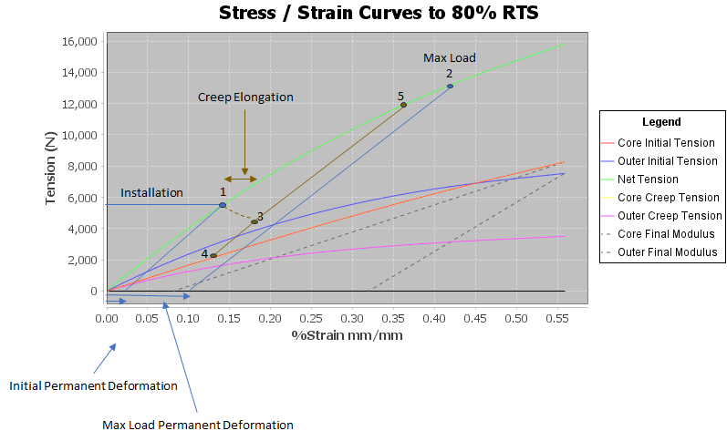
At Installation time, the wire will move to point #1, where a small amount of permanent strain will develop in the wire. This is found by removing all tension from the wire (tension=0).
From Point #1, if the maximum stress loadcase is applied to the wire, it will then stretch to point #2. Here the tension of the wire as a whole and by material (inner/outer) is recorded. This develops the maximum load permanent deformation in the wire (inner and outer materials), which can be determined by removing the tension from the wire (tension=0).
After installation time at point #1, wire creep can be developed in the wire if the wire does not see a maximum load scenario, but rather sees everyday tensions instead for the next 10 years. After 10 years, the amount of additional creep development is considered negligible by the utility industry. For sake of convenience, the everyday temperature used for these tests is the same as the installation temperature. It can be different, but there is no specific test required here for different average daily temperatures.
Using the creep nonlinear polynomials for the wire (inner/outer), the wire's state will move from point #1 to point #3. Here the net permanent deformation can be determined by setting tension=0 again. From this point, the thermal condition (100 C in these tests) can be determined. This can be a worst wire sag condition than after load, in some cases. So it must always be evaluated, just in case. This results in point #4 in the chart.
The other thing that can happen to a wire that has seen everyday creep, is that it can then see a maximum load scenario. It is important for the software to correctly handle this situation. This generally requires the wire to follow the final modulus curve up until the point (#5 in the chart) where it determines that the Initial curve is reached (if applicable). If the wire is loaded beyond what the Initial Curve would have estimated, it must then follow the Initial Curve to the required point; perhaps up to and including point #2. In no case should the software continue on the final modulus curve above the Initial curve.
In addition to calculating static loads for specific weather load cases (including wind direction), it is also important to assess changes when the attached structures deflect. This is important in Multi-Pole analysis and Load Nonlinearity generally.
Evaluation tests should include:
- Values for:
- Tension at both support structures
- Horizontal tension
- Line of sight sag
- Vertical sag (sag below lowest attachment support)
- Horizontal and vertical loads per meter on the wire.
- Effective bundle diameter
- Unstretched length (where possible)
- For software that cannot do this, a value for it will be set and provided for the software to generate the other required test results.
- Weather loads that test wire
- stretching behavior with different possible loads in the vertical and transverse planes.
- 400 pascals wind pressure
- 12.5mm radial ice accretion
- Ice Density=900 kg/m3
- Line of Sight and Vertical Sags will be collected for sag comparisons
- Thermal condition (100C)
- Level spans of varied lengths
- 20 m
- 40 m
- 60 m
- 80 m
- 100 m
- 120 m
- 140 m
- 160 m
- 180 m
- 200 m
- 400 m
- 600 m
- 800 m
- 1000 m
- 1500 m
- 2000 m
- Unlevel spans
- 100m fixed Span Length (horizontal distance)
- varied elevation changes
- 0 m (for reference purposes)
- 5 m
- 10 m
- 20 m
- 30 m
- 40 m
- 50 m
- 100 m
- 200 m
- measure both upper and lower attachment point tensions plus sags described above
- Observance of any birdcaging effects for multi-material wires and what temperature they occurred. Increments of 10C temperature increments are recommended.
- If birdcaging criteria is modifiable, test at different values than default to ensure change is respected. Otherwise state values used and justification.
- Wire types:
- All aluminum
- 566.5 Dahlia AAC
- 336.4 Tulip ASC
- 4/0 Oxlip AAC
- 1/0 Poppy AAC
- Aluminum and Steel
- 795 Drake ACSR
- 477 Hawk
- 4/0 Penguin ACSR
- 3/0 Pigeon ACSR
- 1/0 Raven ACSR
- #2 Sparrow AW 6/1
- Multiplex wires
- #2 ACSR Triplex (Clam)
- 1/0 ACSR Triplex (Ranella)
- 4/0 ACSRcQuadruplex (Stallion)
- Copper
- 750 kcmil 37 strands
- 4/0 7 strands
- 1/0 7 strands
- #6 7 strands
- Steel
- 3/16 inch 7 Strands Grades HS,EHS
- 1/4 inch 7 Strands Grades HS,EHS
- 3/8 inch 7 Strands Grades HS,EHS
- 1/2 inch 7 Strands Grades HS,EHS
- 3/4 inch 19 Strands Grades HS,EHS
- Figure 8 Communication Cables (The messenger/strand is mechanically bonded to a communications cable using extruded PVC.)
- Corning Figure-8 (Non-Armoured) 2-72 Fibres, 1/4 inch EHS 7 Strands Steel
- Wire mass=0.296kg/m
- Strength=29581N
- Diameter=22.1mm
- Cross sectional area=22.71mm2
- Thermal exp. 1.152e-3
- Final Modulus=1723.69 MPa/100
- Stress polynomials= 11.23,1283.33,1967.34,-4414.84,2343.4 MPa/100
- Creep Polynomials=11.23,1283.33,1967.34,-4414.84,2343.4 MPa/100
- Corning Figure-8 (Armoured) 73-96 Fibres, 1/4 inch EHS 7 Strands Steel
- Wire mass=0.432kg/m
- Strength=29581N
- Diameter=27.69mm
- Cross sectional area=22.71mm2
- Thermal exp. 1.152e-3
- Final Modulus=1723.69 MPa/100
- Stress polynomials= 11.23,1283.33,1967.34,-4414.84,2343.4 MPa/100
- Creep Polynomials=11.23,1283.33,1967.34,-4414.84,2343.4 MPa/100
- Corning Figure-8 Copper 200 Pairs 24 gauge, 1/4 inch EHS 7 Strands Steel
- Wire mass=1.302 kg/m
- Strength=29581N
- Diameter=40.64mm
- Cross sectional area=22.71mm2
- Thermal exp. 1.152e-3
- Final Modulus=1723.69 MPa/100
- Stress polynomials= 11.23,1283.33,1967.34,-4414.84,2343.4 MPa/100
- Creep Polynomials=11.23,1283.33,1967.34,-4414.84,2343.4 MPa/100
- Dielectric cables with a fiberglass core messenger (e.g. Kevlar yarn)
- ADSS cable from AFL AE2889CO31BA5
- Wire mass=0.393kg/m
- Strength=24225N
- Diameter=22.61mm
- Cross sectional area=401.16mm2
- Thermal exp. 2.9069e-3
- Final Modulus=32.2 MPa/100
- Stress polynomials= 0.0, 29.83, 0.0,0.0,0.0
- Creep Polynomials=0.0,24.86,0.0,0.0,0.0
- ADSS cable from Corning 2-72 Fibre SOLO Short Span Single Jacket Self Supporting, Kevlar Messenger 072EN4-T3S00A20
- Wire mass=0.092 kg/m
- Strength=3963 N
- Diameter=10.9 mm
- Cross sectional area=401.16mm2
- Thermal exp. 2.3724E-4 m/m/C
- Final Modulus=51.12 MPa/100
- Stress polynomials= -0.36, 51.12, 0.0,0.0,0.0
- Creep Polynomials=-1.08,51.12,0.0,0.0,0.0
- ADSS cable from Corning 73-96 Fibre SOLO Dual Jacket (Span Code F)Self Supporting, Kevlar Messenger 096EAE-T3F01A20
- Wire mass=0.247 kg/m
- Strength=32063 N
- Diameter=18.39 mm
- Cross sectional area= 264.52 mm2
- Thermal exp. 2.8692E-4 m/m/C
- Final Modulus=140.04 MPa/100
- Stress polynomials= -11.07, 140.04, 0.0,0.0,0.0
- Creep Polynomials=-22.14,140.04,0.0,0.0,0.0
- ADSS cable from Corning 240-288 Fibre SOLO Dual Jacket (Span Code E)Self Supporting, Kevlar Messenger 288EAE-T3E01A20
- Wire mass=0.46 kg/m
- Strength=44949 N
- Diameter=25.3 mm
- Cross sectional area= 503.22 mm2
- Thermal exp. 2.3976E-4 m/m/C
- Final Modulus=92.59 MPa/100
- Stress polynomials= -6.58, 92.59, 0.0,0.0,0.0
- Creep Polynomials=-13.16,92.59,0.0,0.0,0.0
- Different Wire Configurations
- Spaced Aerial Cable tests using one wire type.
- Standard Communication Bundles
- Wire states:
- Initial
- Final after Creep
- Average day temperature for creep should be 15C - Point #3
- Maximum weather load from the Initial state tests - Point #5
- Test 100C Thermal condition - Point #4
- Final after Load. This test will ensure, for each wire type, that the wires will perform correctly under different loads and different permanent strain conditions in each of the materials used in the wires.
- Test 100C Thermal condition after maximum weather load from the Initial state tests.
- Structure Movement
- To ensure that multi-pole scenarios using Load Nonlinearity will be calculated properly, each wire/cable under the above scenarios, after maximum weather load, should be recalculated under structure movement scenarios. Since each model may be oriented differently, the below suggestions should be adequately tests.
- X dir - 1.0m
- Y dir - 1.0m
- Z dir - 1.0m
To properly evaluate Sag & Tension calculations, some details need to be taken into account. The software needs to model all wires/messengers in a way that they are typically installed, assuming new material. When wires are installed and sagged in one operation in a line section of several equal or unequal, level or unlevel spans, the structures between the dead-ends of the stringing section support the wire with stringing sheaves or blocks or loose hardware clamps, that permits the wire to move freely between spans. Once the wire’s tension is set to the desired value, the conductor is secured to its supporting insulator or connection hardware. This fixes the amount of wire used between the structure supports under initial stringing conditions (Unstretched Length). Software will need to be configured to respect this assumption. Scenarios for testing existing wire that has already seen load events or time, is out of scope for this document.
For sag-tension calculation for communication cables, the exact same procedure needs to be followed as for conductors, for the messenger alone. After the messenger unstretched length is fixed, the communication cables get lashed onto the messenger. All loadcases are calculated, and wire stretch scenarios are calculated using this additional cable weight and larger bundle diameter. This is representative of how communication cables are strung in the field.
The tension settings sugested so that results can be compared between software are listed as follows for level span tests and unlevel span tests. While most of the shorter span length tests use a consistent tension value, higher span length tests needed higher tensions to properly suspend the wire/cable in the span.
For ADSS type wires/cables, the default tension is usually defined as %sag, whereas other wires are usually %RTS.
Wire Stringing Tensions(N) by Span Lengths(m) for Level Span Tests @ 15°C
|
WIRE_DESCR |
20 |
40 |
60 |
80 |
100 |
120 |
140 |
160 |
180 |
200 |
400 |
600 |
800 |
1000 |
1500 |
2000 |
|
556.5 kcmil 19/0 Strands DAHLIA AAC |
4337 |
4337 |
4337 |
4337 |
4337 |
4337 |
4337 |
4337 |
4337 |
4337 |
4337 |
4337 |
6011 |
7513 |
11270 |
15027 |
|
336.4 kcmil 19/0 Strands TULIP AAC |
4337 |
4337 |
4337 |
4337 |
4337 |
4337 |
4337 |
4337 |
4337 |
4337 |
4337 |
4337 |
6011 |
7513 |
11270 |
15027 |
|
4 /O AWG 7/0 Strands OXLIP AAC |
4337 |
4337 |
4337 |
4337 |
4337 |
4337 |
4337 |
4337 |
4337 |
4337 |
4337 |
4337 |
6011 |
7513 |
11270 |
15027 |
|
1 /O AWG 7/0 Strands POPPY AAC |
4337 |
4337 |
4337 |
4337 |
4337 |
4337 |
4337 |
4337 |
4337 |
4337 |
4337 |
4337 |
6011 |
7513 |
11270 |
15027 |
|
795 kcmil 26/7 Strands DRAKE ACSR |
14011 |
14011 |
14011 |
14011 |
14011 |
14011 |
14011 |
14011 |
14011 |
14011 |
14011 |
14011 |
14011 |
14011 |
23617 |
31489 |
|
477 kcmil 26/7 Strands HAWK ACSR |
14011 |
14011 |
14011 |
14011 |
14011 |
14011 |
14011 |
14011 |
14011 |
14011 |
14011 |
14011 |
14011 |
14011 |
23617 |
31489 |
|
4 /O AWG 6/1 Strands PENGUIN ACSR |
14011 |
14011 |
14011 |
14011 |
14011 |
14011 |
14011 |
14011 |
14011 |
14011 |
14011 |
14011 |
14011 |
14011 |
23617 |
31489 |
|
3 /O AWG 6/1 Strands PIGEON ACSR |
14011 |
14011 |
14011 |
14011 |
14011 |
14011 |
14011 |
14011 |
14011 |
14011 |
14011 |
14011 |
14011 |
14011 |
23617 |
31489 |
|
1 /O AWG 6/1 Strands RAVEN ACSR |
14011 |
14011 |
14011 |
14011 |
14011 |
14011 |
14011 |
14011 |
14011 |
14011 |
14011 |
14011 |
14011 |
14011 |
23617 |
31489 |
|
2 AWG 6/1 Strands SPARROW ACSR |
14011 |
14011 |
14011 |
14011 |
14011 |
14011 |
14011 |
14011 |
14011 |
14011 |
14011 |
14011 |
14011 |
14011 |
23617 |
31489 |
|
750 kcmil 37 Strands Copper |
22285 |
22285 |
22285 |
22285 |
22285 |
22285 |
22285 |
22285 |
22285 |
22285 |
22285 |
22285 |
26670 |
33338 |
50008 |
66677 |
|
4 /O AWG 7 Strands Copper |
22285 |
22285 |
22285 |
22285 |
22285 |
22285 |
22285 |
22285 |
22285 |
22285 |
22285 |
22285 |
26670 |
33338 |
50008 |
66677 |
|
1 /O AWG 7 Strands Copper |
22285 |
22285 |
22285 |
22285 |
22285 |
22285 |
22285 |
22285 |
22285 |
22285 |
22285 |
22285 |
26670 |
33338 |
50008 |
66677 |
|
6 AWG 7 Strands Copper |
22285 |
22285 |
22285 |
22285 |
22285 |
22285 |
22285 |
22285 |
22285 |
22285 |
22285 |
22285 |
26670 |
33338 |
50008 |
66677 |
|
#2 AWG Triplex #2 AWG 1350 Neutral 0.76 inches POLY CLAM Multiplex |
900 |
900 |
900 |
900 |
900 |
900 |
900 |
900 |
900 |
900 |
1335 |
2003 |
2671 |
3338 |
5008 |
6677 |
|
1/0 AWG Triplex #2 AWG ACSR Neutral 0.96 inches POLY RANELLA Multiplex |
900 |
900 |
900 |
900 |
900 |
900 |
900 |
900 |
900 |
900 |
2083 |
3125 |
4167 |
5209 |
7814 |
10419 |
|
4/0 AWG Quadraplex 4/0 AWG ACSR Neutral 1.48 inches POLY STALLION Multiplex |
900 |
900 |
900 |
1212 |
1515 |
7465 |
7796 |
8131 |
8470 |
8814 |
12501 |
16682 |
21443 |
26918 |
45130 |
74422 |
|
3/4 inch HS 19 Strands Steel |
36297 |
72596 |
72598 |
72600 |
72604 |
72608 |
72613 |
72619 |
72626 |
72633 |
72751 |
72947 |
73222 |
73577 |
74818 |
76579 |
|
3/4 inch EHS 19 Strands Steel |
51866 |
103733 |
103734 |
103736 |
103739 |
103742 |
103745 |
103749 |
103754 |
103759 |
103841 |
103978 |
104171 |
104418 |
105280 |
106495 |
|
1/2 inch HS 7 Strands Steel |
28357 |
28357 |
28357 |
56715 |
56716 |
56717 |
56718 |
56720 |
56722 |
56724 |
56754 |
56804 |
56874 |
56965 |
57280 |
57723 |
|
1/2 inch EHS 7 Strands Steel |
28357 |
28357 |
28357 |
56715 |
56716 |
56717 |
56718 |
56720 |
56722 |
56724 |
56754 |
56804 |
56874 |
56965 |
57280 |
57723 |
|
3/8 inch HS 7 Strands Steel |
9341 |
9341 |
18683 |
18683 |
18684 |
18685 |
18686 |
18687 |
18689 |
18690 |
18716 |
18759 |
18818 |
18895 |
19164 |
19545 |
|
3/8 inch EHS 7 Strands Steel |
9341 |
9341 |
18683 |
18683 |
18684 |
18685 |
18686 |
18687 |
18689 |
18690 |
18716 |
18759 |
18818 |
18895 |
19164 |
19545 |
|
1/4 inch HS 7 Strands Steel |
4893 |
4893 |
4893 |
4893 |
4893 |
9787 |
9787 |
9788 |
9788 |
9789 |
9798 |
9814 |
9837 |
9866 |
9966 |
10108 |
|
1/4 inch EHS 7 Strands Steel |
4893 |
4893 |
4893 |
4893 |
4893 |
9787 |
9787 |
9788 |
9788 |
9789 |
9798 |
9814 |
9837 |
9866 |
9966 |
10108 |
|
3/16 inch HS 7 Strands Steel |
2535 |
2535 |
2535 |
2535 |
5071 |
5071 |
5071 |
5071 |
5072 |
5072 |
5079 |
5090 |
5106 |
5126 |
5197 |
5297 |
|
3/16 inch EHS 7 Strands Steel |
3549 |
3549 |
3549 |
3549 |
7099 |
7099 |
7099 |
7099 |
7099 |
7100 |
7105 |
7113 |
7124 |
7138 |
7188 |
7259 |
|
Figure-8 (Non-Armoured) 2-72 Fibres, 1/4 inch EHS 7 Strands Steel |
5916 |
5916 |
5916 |
5916 |
5916 |
5916 |
5916 |
5916 |
5916 |
5916 |
5916 |
5916 |
5916 |
5916 |
5916 |
5916 |
|
Figure-8 (Armoured) 73-96 Fibres, 1/4 inch EHS 7 Strands Steel |
5916 |
5916 |
5916 |
5916 |
5916 |
5916 |
5916 |
5916 |
5916 |
5916 |
5916 |
5916 |
5916 |
5916 |
5916 |
8347 |
|
Figure-8 Copper 200 Pairs 24 gauge, 1/4 inch EHS 7 Strands Steel |
5916 |
5916 |
5916 |
5916 |
5916 |
5916 |
5916 |
5916 |
5916 |
5916 |
5916 |
7555 |
10074 |
12592 |
18889 |
25185 |
|
AFL ADSS AE2889CO31BA5 |
964 |
1928 |
2892 |
3856 |
4820 |
5784 |
6748 |
7713 |
8677 |
9641 |
19282 |
28924 |
38565 |
48207 |
72310 |
96414 |
|
2-72 Fibre SOLO Short Span Single Jacket Self Supporting, Kevlar Messenger 072EN4-T3S00A20 |
226 |
452 |
679 |
905 |
1132 |
1358 |
1584 |
1811 |
2037 |
2264 |
4528 |
6792 |
9056 |
11320 |
16981 |
22641 |
|
73-96 Fibre SOLO Dual Jacket (Span Code F)Self Supporting, Kevlar Messenger 096EAE-T3F01A20 |
606 |
1212 |
1818 |
2424 |
3031 |
3637 |
4243 |
4849 |
5455 |
6062 |
12124 |
18186 |
24248 |
30310 |
45465 |
60621 |
|
240-288 Fibre SOLO Dual Jacket (Span Code E)Self Supporting, Kevlar Messenger 288EAE-T3E01A20 |
1128 |
2256 |
3385 |
4513 |
5642 |
6770 |
7899 |
9027 |
10155 |
11284 |
22568 |
33852 |
45137 |
56421 |
84632 |
112843 |
|
Bundle #1 052/266.8 |
27249 |
27249 |
27250 |
27251 |
27252 |
27254 |
27256 |
27258 |
27260 |
27263 |
27308 |
27382 |
27487 |
27622 |
28093 |
28762 |
|
336.4 TULIP AAC - Twisted Pair |
16414 |
16416 |
16420 |
16425 |
16432 |
16441 |
16451 |
16463 |
16476 |
16491 |
16727 |
17128 |
17705 |
18474 |
24101 |
33461 |
|
336.4 TULIP AAC - Twin Horiz |
16414 |
16417 |
16421 |
16428 |
16437 |
16447 |
16460 |
16474 |
16490 |
16508 |
16798 |
17292 |
18007 |
18969 |
25398 |
36276 |
|
336.4 TULIP AAC - Twin Vert |
16414 |
16417 |
16421 |
16428 |
16437 |
16447 |
16460 |
16474 |
16490 |
16508 |
16798 |
17292 |
18007 |
18969 |
25398 |
36276 |
|
336.4 TULIP AAC - Triangle |
19150 |
19154 |
19161 |
19170 |
19182 |
19197 |
19214 |
19234 |
19257 |
19283 |
19689 |
20382 |
21383 |
26393 |
38866 |
54851 |
|
336.4 TULIP AAC - Square |
21886 |
21891 |
21900 |
21912 |
21927 |
21946 |
21969 |
21995 |
22024 |
22057 |
22581 |
23473 |
29145 |
34702 |
50900 |
71537 |
|
336.4 TULIP AAC - Diamond |
21886 |
21891 |
21900 |
21912 |
21927 |
21946 |
21969 |
21995 |
22024 |
22057 |
22581 |
23473 |
29145 |
34702 |
50900 |
71537 |
|
336.4 TULIP AAC - Hexagon |
27358 |
27365 |
27376 |
27393 |
27414 |
27439 |
27470 |
27505 |
27545 |
27589 |
28297 |
34930 |
42118 |
49884 |
72306 |
100383 |
|
336.4 TULIP AAC - Octagon |
32830 |
32840 |
32856 |
32879 |
32909 |
32945 |
32988 |
33037 |
33093 |
33155 |
38148 |
47310 |
57220 |
67951 |
99081 |
138396 |
Wire Stringing Tensions(N) for 100m Span by Elevation Differences(m) @ 15°C. Tension measured at the higher elevation attachment point
|
WIRE_DESCR |
0 |
5 |
10 |
20 |
40 |
30 |
50 |
100 |
200 |
|
556.5 kcmil 19/0 Strands DAHLIA AAC |
8674 |
8674 |
8674 |
8674 |
8674 |
8674 |
8674 |
8674 |
8674 |
|
336.4 kcmil 19/0 Strands TULIP AAC |
8674 |
8674 |
8674 |
8674 |
8674 |
8674 |
8674 |
8674 |
8674 |
|
4 /O AWG 7/0 Strands OXLIP AAC |
8674 |
8674 |
8674 |
8674 |
8674 |
8674 |
8674 |
8674 |
8674 |
|
1 /O AWG 7/0 Strands POPPY AAC |
8674 |
8674 |
8674 |
8674 |
8674 |
8674 |
8674 |
8674 |
8674 |
|
795 kcmil 26/7 Strands DRAKE ACSR |
28022 |
28022 |
28022 |
28022 |
28022 |
28022 |
28022 |
28022 |
28022 |
|
477 kcmil 26/7 Strands HAWK ACSR |
28022 |
28022 |
28022 |
28022 |
28022 |
28022 |
28022 |
28022 |
28022 |
|
4 /O AWG 6/1 Strands PENGUIN ACSR |
28022 |
28022 |
28022 |
28022 |
28022 |
28022 |
28022 |
28022 |
28022 |
|
3 /O AWG 6/1 Strands PIGEON ACSR |
28022 |
28022 |
28022 |
28022 |
28022 |
28022 |
28022 |
28022 |
28022 |
|
1 /O AWG 6/1 Strands RAVEN ACSR |
28022 |
28022 |
28022 |
28022 |
28022 |
28022 |
28022 |
28022 |
28022 |
|
2 AWG 6/1 Strands SPARROW ACSR |
28022 |
28022 |
28022 |
28022 |
28022 |
28022 |
28022 |
28022 |
28022 |
|
750 kcmil 37 Strands Copper |
44570 |
44570 |
44570 |
44570 |
44570 |
44570 |
44570 |
44570 |
44570 |
|
4 /O AWG 7 Strands Copper |
44570 |
44570 |
44570 |
44570 |
44570 |
44570 |
44570 |
44570 |
44570 |
|
1 /O AWG 7 Strands Copper |
44570 |
44570 |
44570 |
44570 |
44570 |
44570 |
44570 |
44570 |
44570 |
|
6 AWG 7 Strands Copper |
44570 |
44570 |
44570 |
44570 |
44570 |
44570 |
44570 |
44570 |
44570 |
|
#2 AWG Triplex #2 AWG 1350 Neutral 0.76 inches POLY CLAM Multiplex |
1800 |
1800 |
1800 |
1800 |
1800 |
1800 |
1800 |
1800 |
2460 |
|
1/0 AWG Triplex #2 AWG ACSR Neutral 0.96 inches POLY RANELLA Multiplex |
1800 |
1800 |
1800 |
1800 |
1800 |
1800 |
1800 |
2230 |
3840 |
|
4/0 AWG Quadraplex 4/0 AWG ACSR Neutral 1.48 inches POLY STALLION Multiplex |
3030 |
3146 |
3270 |
3536 |
4152 |
3832 |
4496 |
6490 |
11172 |
|
3/4 inch HS 19 Strands Steel |
72594 |
72594 |
72594 |
72594 |
72594 |
72594 |
72594 |
72594 |
72594 |
|
3/4 inch EHS 19 Strands Steel |
103732 |
103732 |
103732 |
103732 |
103732 |
103732 |
103732 |
103732 |
103732 |
|
1/2 inch HS 7 Strands Steel |
56714 |
56714 |
56714 |
56714 |
56714 |
56714 |
56714 |
56714 |
56714 |
|
1/2 inch EHS 7 Strands Steel |
56714 |
56714 |
56714 |
56714 |
56714 |
56714 |
56714 |
56714 |
56714 |
|
3/8 inch HS 7 Strands Steel |
18682 |
18682 |
18682 |
18682 |
18682 |
18682 |
18682 |
18682 |
18682 |
|
3/8 inch EHS 7 Strands Steel |
18682 |
18682 |
18682 |
18682 |
18682 |
18682 |
18682 |
18682 |
18682 |
|
1/4 inch HS 7 Strands Steel |
9786 |
9786 |
9786 |
9786 |
9786 |
9786 |
9786 |
9786 |
9786 |
|
1/4 inch EHS 7 Strands Steel |
9786 |
9786 |
9786 |
9786 |
9786 |
9786 |
9786 |
9786 |
9786 |
|
3/16 inch HS 7 Strands Steel |
5070 |
5070 |
5070 |
5070 |
5070 |
5070 |
5070 |
5070 |
5070 |
|
3/16 inch EHS 7 Strands Steel |
7098 |
7098 |
7098 |
7098 |
7098 |
7098 |
7098 |
7098 |
7098 |
|
Figure-8 (Non-Armoured) 2-72 Fibres, 1/4 inch EHS 7 Strands Steel |
11832 |
11832 |
11832 |
11832 |
11832 |
11832 |
11832 |
11832 |
11832 |
|
Figure-8 (Armoured) 73-96 Fibres, 1/4 inch EHS 7 Strands Steel |
11832 |
11832 |
11832 |
11832 |
11832 |
11832 |
11832 |
11832 |
11832 |
|
Figure-8 Copper 200 Pairs 24 gauge, 1/4 inch EHS 7 Strands Steel |
11832 |
11832 |
11832 |
11832 |
11832 |
11832 |
11832 |
11832 |
11832 |
|
AFL ADSS AE2889CO31BA5 |
9640 |
3290 |
2162 |
1418 |
1060 |
1162 |
1482 |
1626 |
2800 |
|
2-72 Fibre SOLO Short Span Single Jacket Self Supporting, Kevlar Messenger 072EN4-T3S00A20 |
2264 |
772 |
508 |
332 |
248 |
272 |
348 |
382 |
656 |
|
73-96 Fibre SOLO Dual Jacket (Span Code F)Self Supporting, Kevlar Messenger 096EAE-T3F01A20 |
6062 |
2068 |
1360 |
892 |
666 |
730 |
932 |
1022 |
1760 |
|
240-288 Fibre SOLO Dual Jacket (Span Code E)Self Supporting, Kevlar Messenger 288EAE-T3E01A20 |
11284 |
3850 |
2532 |
1660 |
1240 |
1362 |
1736 |
1904 |
3278 |
|
Bundle #1 052/266.8 |
27248 |
27248 |
27248 |
27248 |
27248 |
27248 |
27248 |
27248 |
27248 |
|
336.4 TULIP AAC - Twisted Pair |
21884 |
21884 |
21884 |
21884 |
21884 |
21884 |
21884 |
21884 |
21884 |
|
336.4 TULIP AAC - Twin Horiz |
21884 |
21884 |
21884 |
21884 |
21884 |
21884 |
21884 |
21884 |
21884 |
|
336.4 TULIP AAC - Twin Vert |
21884 |
21884 |
21884 |
21884 |
21884 |
21884 |
21884 |
21884 |
21884 |
|
336.4 TULIP AAC - Triangle |
21884 |
21884 |
21884 |
21884 |
21884 |
21884 |
21884 |
21884 |
21884 |
|
336.4 TULIP AAC - Square |
21884 |
21884 |
21884 |
21884 |
21884 |
21884 |
21884 |
21884 |
21884 |
|
336.4 TULIP AAC - Diamond |
21884 |
21884 |
21884 |
21884 |
21884 |
21884 |
21884 |
21884 |
21884 |
|
336.4 TULIP AAC - Hexagon |
21884 |
21884 |
21884 |
21884 |
21884 |
21884 |
21884 |
21884 |
21884 |
|
336.4 TULIP AAC - Octagon |
21884 |
21884 |
21884 |
21884 |
21884 |
21884 |
21884 |
21884 |
27536 |