Sags and Tensions Calculator
Sags and Tensions Tool
The Sags and Tensions Tool exposes some of the power behind Quick Pole's Sag and Tension calculations. It can be used to evaluate existing conditions and predict future reactions to loads, to build Stringing Tension Tables for your Organization or to do "what if?" analyses. A subset of these Sag and Tension options are available under the "Edit Tensions" options for wire attachments in Quick Pole designs. This particular Tool has a much wider purpose than that required for wire attachments within a Project. The ability to help Organizations determine how to determine the maximum load and stringing tension for wires they would like to use is the second major purpose of this tool.
The Tool is broken out into several separate Window Tabs exposing different Sag and Tension input parameters and different views on the results.
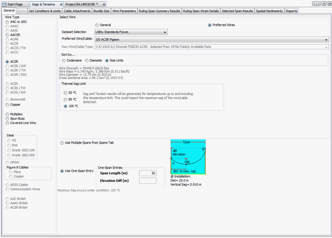
General Tab
In this Tab you select the exact Wire or Self Supporting Cable you wish to evaluate. The left-hand side of Radio Buttons serves to filter the listing of wires in the Wire selection box by category. Within the selected Dataset Selection, only Radio Buttons that correspond to valid categories will be enabled and able to be selected as filters. To aid the selection of a wire, you can also have the wire selection box's listing sorted by Codename, Diameter or Size. Codename and Size are optional in the Database, but are valuable as useful selection and sorting attributes if present.
There are two different Dataset categories available for selection; those defined as standards by an Organization as Preferred Wires and "General" wires which are not. Each category of Dataset will have a Dataset selection for each Organization defined in the DataManager. There may be no wires defined for some Dataset and Organization category combinations.
Thermal Sag Limit
This Tool evaluates wires and Self Supporting Cables under a wide range of conditions. One of these variables is temperature with no wind or ice loading. As all materials will have more sag and less tension at higher temperature, it is important to tell this Tool how high in temperature to evaluate Sags and Tensions. Since you could want to know what the maximum Sag condition and value is, you want to limit tests to conditions you want to use the wire/cable. The Thermal Sag Limit Radio Buttons will automatically change to default values based on the Wire Type Category selected on the left-hand side. You may want to change the default value. which is why this Tool exposes the default value calculated and enables you to change it.
Default Values:
- 50 °C - wires/cables for communication purposes and other wires not designed to carry current.
- 50 °C - multiplex (Triplex, Quadruplex) wires with same size neutral wire. Assumed that the neutral is designed to carry less than 35% rated amperage under non-fault conditions. Smaller neutral wires would not qualify.
- 80 °C - covered wires designed to carry current.
- 100 °C - bare wires designed to carry current
Span Entries
The distance between poles (span length) is a key factor in Sag and Tension calculations. This Tool provides a simple one span length and attachment elevation difference entry, or a multi-span entry available on a separate Window Tab. Select the entry option you wish.
Spans Tab
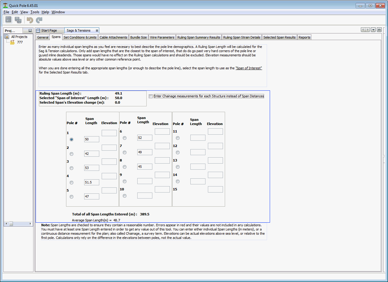
In this Window Tab you can enter many poles in sequence in a Pole Line. Please Note that you should not include poles that go past a deadend framed structure (for the wire/cable you are evaluating). This entry means is intended for a section of pole line that contains tangent and cornered poles, but not head guyed or otherwise deadended poles. The reason is that poles past deadends have no impact on the Ruling Span for the poles prior to the deadend. The concept of a "Ruling Span" is that when you have many pole spans in a pole line with varying span lengths, there is a weighted averaging that happens to the sags and tensions in the line that becomes similar to the same pole line with all poles having the same span length - the Ruling Span. Quick Pole uses the Ruling Span formula provided by Rural Utility Services (RUS) Design Bulletin 1724E-200.

The Ruling Span is calculated for the Pole Spans entered and is displayed near the top. As additional information the total of all spans entered and the average span length are displayed near the bottom. Each span is able to be selected with the Radio Buttons between the sequential pole numbers. For greater certainty the selected span length and elevation height difference between the attachment points on the adjacent poles is repeated near the top. The significance of selecting a span is that it triggers the "Selected Span Results" tab to display results specific to that span. The other tabs "Ruling Span Summary Results" and "Ruling Span Strain Details" go into great depth displaying the calculated results for the Ruling Span.
It should be noted that while Quick Pole will calculate a Ruling Span distance and generate results for a span of the same length, the Ruling Span value is not actually used in the Sag & Tension calculations. It uses the actual installation stringing tension as it's starting point for each span and then calculates the Sag & Tension values. The concept of a Ruling Span was developed historically as a way of recognizing the effects of hanging insulators and wooden poles deflecting and "averaging" the effect of shorter and longer spans under loaded conditions.
If you have pole span data captured in typical survey format, by selecting the "Enter Chainage..." Checkbox you can enter the values collected directly, as opposed to calculating each span separately. This helps reduce input errors.
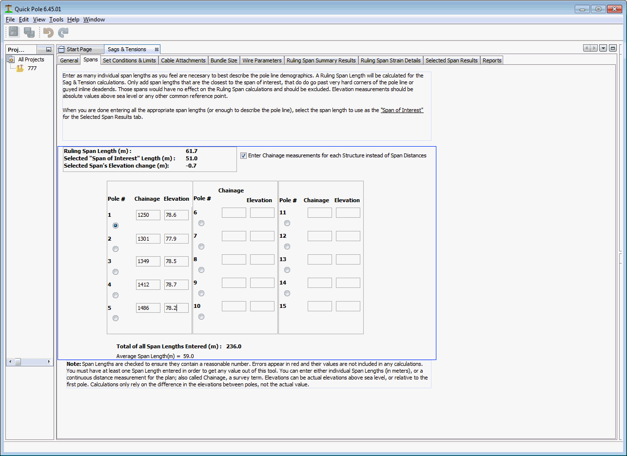
The chainage measurement is the horizontal distance measured between the poles, not the actual physical distance between the poles. They would be the same measurements if the poles were on level ground and the attachment heights were the same. Surveyors that are familiar with surveying roadways or properties would have no trouble providing the measurements this way. This tab is geared towards them.
The elevations work the same using chainage as they do without. You can enter the actual elevations of the attachments or you can enter the differences between the poles. If the poles are all framed the same and the attachments are always at the same height, you can select to enter the elevations of the base of the pole if that is easier. Otherwise the attachment's elevation or elevation difference should be entered. You must enter all elevations consistently the same way in this tab.
Set Conditions and Limits Tab
Other than possibly attaching cables to the selected wire or self supporting cable, this tab is where all loadings and tension requirements are defined.
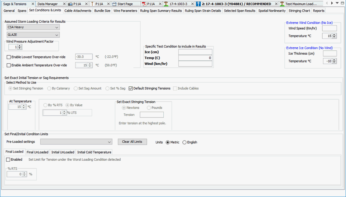
Assumed Storm Loading Criteria
In this upper left-hand corner of this tab, you select the main Storm Criteria to use for the calculations. There are several North American pre-defined criteria to choose from. Optionally you can change the type of frozen precipitation as well, but this is seldom used as the thickness of frozen precipitation does not change to match. A summary of the loads derived from the Storm Criteria and the frozen precipitation type are shown to the right of these controls. The Wind Pressure Adjustment Factor will impact the wind pressure applied to the attachment.
Wind Pressure Adjustment Factor
The Wind Pressure Adjustment Factor is available to increase or to decrease the exposure of the attachment to wind pressure; compared to the default value based on the Storm Criteria. This entry effects the Assumed Storm Load related wind pressure, the Specific Test Condition's related wind pressure plus that from the Extreme Wind Condition, if entered.
Specific Test Condition
This is an additional loading condition that you can enter that will be included in the Sag and Tension results. The ice thickness represents the thickness of the frozen precipitation chosen in this tab and can be any value, or zero. The temperature entered, ice and wind will be all evaluated as one set of variables defining this particular loading condition. Wind is entered in wind speed instead of wind pressure, as a convenience. If you want a specific wind pressure value, you will first need to convert it to wind speed. You can use the following formula to assist:
Wind Pressure (Pascals) = 0.055 * WindSpeed2 * Wind Pressure Adjustment Factor
Where Wind Speed is already in kilometers per hour.
Extreme Wind Condition
If a Wind Speed is entered, the combination of wind speed, temperature and no ice loading will be evaluated as an additional loading condition to be evaluated in the Sag and Tension calculations. The Wind Pressure Adjustment Factor will impact the wind pressure applied to the attachment.
Extreme Ice Condition
If a Ice Thickness is entered, the combination of temperature and no wind will be evaluated as an additional loading condition to be evaluated in the Sag and Tension calculations. The type of ice is the same as selected on this tab.
Lowest Temperature Override
If selected, this value will be thew lowest temperature Load Case to be evaluated.
Ambient Temperature Override
If selected, this value will be shown within the set of Load Cases (if not already), plus it will be used to help determine Wire Final Creep results.
Set Exact Initial Tension or Sag Requirements
In the Center area of this Tab you set the criteria for tensioning and sagging the wire or self supporting cable under non-Storm conditions. By default, the "Default Stringing Tensions" Checkbox is selected, as a convenience. If the attachment selected was as a Preferred Wire, the appropriate Stringing Tensions and temperature will be selected from the database. If the attachment is not a Preferred Wire, certain assumptions are made:
- Steel Wires (including Figure 8) are checked to see if they match typical Communication Messenger sizes. If they do, standard Bell stringing tensions are assumed. Otherwise 20% UTS is assumed.
- Communication Service Wires are assumed to be strung to 60 pounds (266 Newtons) tension.
- All Dielectric Self Supporting Cables are assumed to be strung to achieve 1% sag.
- Power Service Wires are assumed to be strung to 134 pounds (600 Newtons).
- Otherwise the tension is assumed to be strung to 15% UTS; based on the assumption that it must be a Power Conductor.
Un-checking the “Default Stringing Tensions” checkbox enables a number of different options for defining the tension. All of these options involve an Unloaded condition; no wind or ice loading. Through the appropriate option, you will be selecting a real condition that could exist in the field, or a new proposed condition that could be measured and set in the field by installation forces. Quick Pole will use this real measurable condition to calculate the appropriate Sags and Tensions and related loads. Sonideft recognizes that some software tools allow the final tensions to be adjusted by tension adjustment factors. Quick Pole will not use that approach as it is difficult to justify and measure in the field.
In the appropriate situation, such as with Communication Messengers, the tension situation can be defined to “Include Cables” via that Checkbox. This is ideal for existing field conditions where additional cables are lashed (attached) to the support wire/messenger today and you want or need to re-tension, or set a specific tension. For instance if today you measured the tension of an existing strand in the field with cables attached and noted the temperature and cable types attached, you could predict all other conditions (temperature, storm load...) from that point; based on these existing conditions. This feature can also be used for existing or proposed Slack Span Construction.
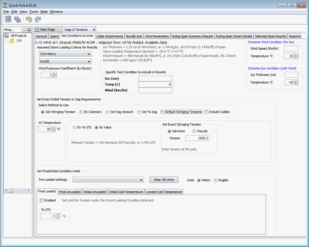
Option #1 - Set Stringing Tension
This is the most common option for attachments as it is easy to measure and set the exact tension at a specific temperature in the field with a dynometer. You can enter a tension amount as a percentage of the breaking strength of the wire/cable or enter a specific value in either imperial (pounds) or metric (Newtons) units.
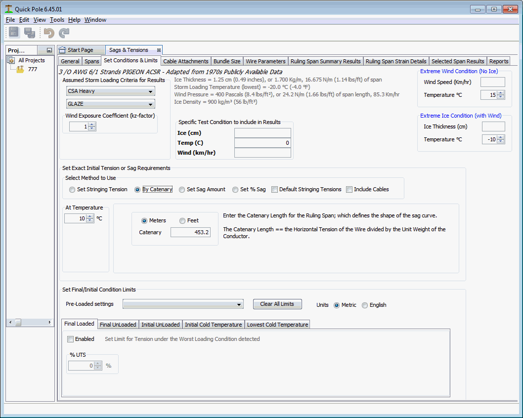
Option #2 - By Catenary
This option is common for Power Conductors when aeolian vibration is of particular concern. The catenary value is a ratio that can be the same for a wide range of wires, while still resulting in different tension amounts. Some guidance for appropriate catenary values can be found in various standards, from the manufacturer or from local experience.
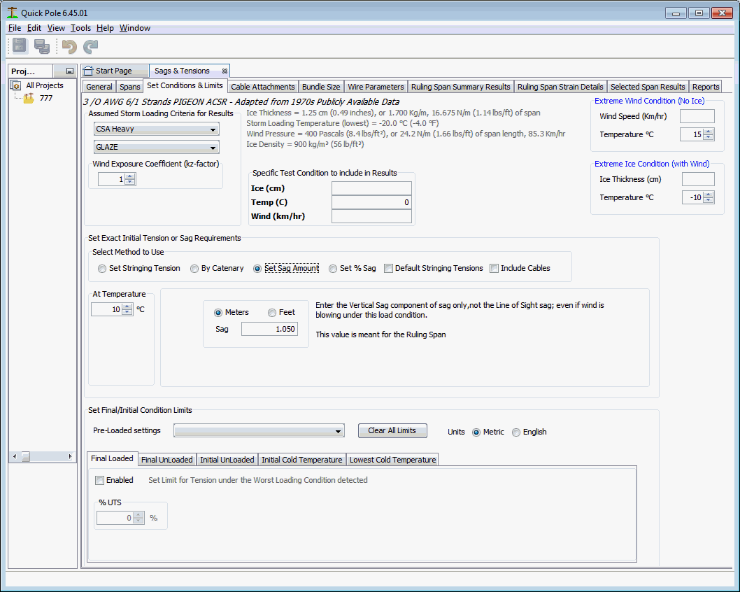
Option #3 - Set Sag Amount
This is very common for modeling of existing conditions you may find in the field. If the wire/cable is already in place, you can get Quick Pole to use this existing tension to determine all other Sags & Tension conditions. The value entered for Sag should be measured at the maximum sag point and is the difference between that height and the attachment height at the lowest pole (if one of the poles is lower than the other).
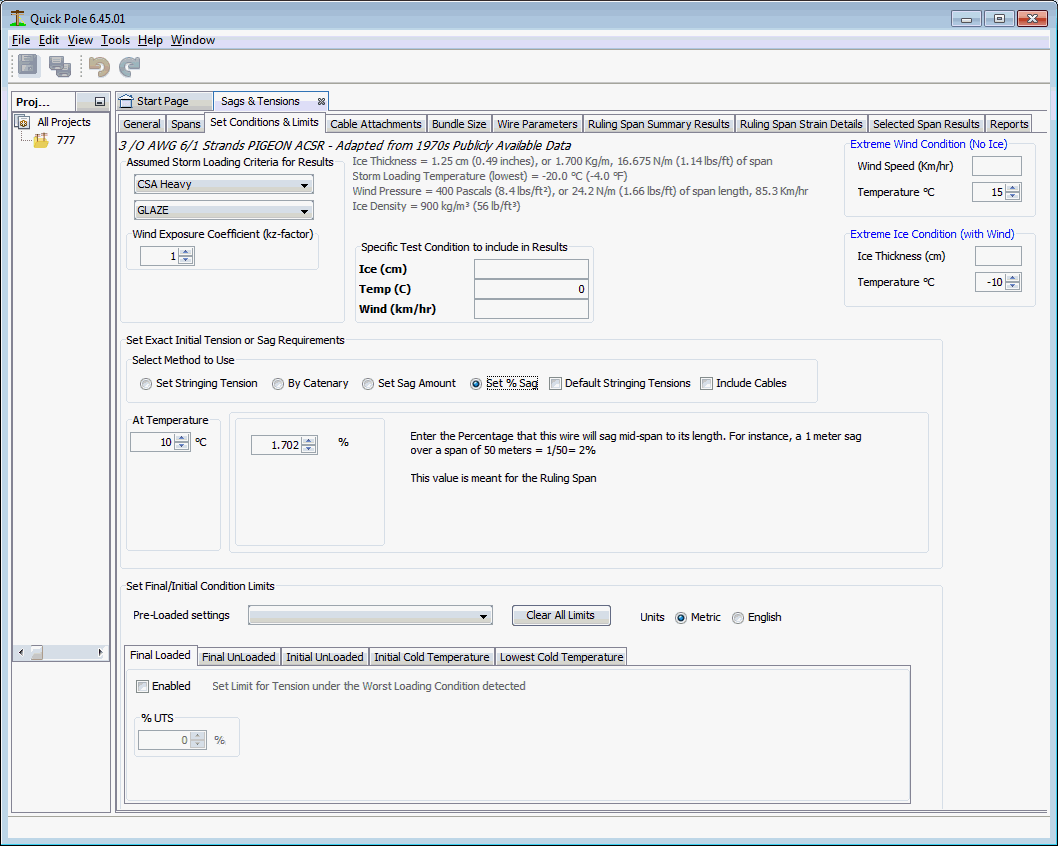
Option #4 - Set % Sag
This option is very common for Service Wires as they are often placed and tensioned until they “look good”. This is also very common for Self-Supporting ADSS cables. In other words the sag amount looks similar to others. This tension option places less tension on shorter spans of wires as the amount of sag is a fixed ratio (percentage) to the span length.
Set Final / Initial Condition Limits
This lower section of this Window Tab is most commonly used to help establish standard tensions for your Organization, similar to SAG-10 and PLS-CADD. There are five sub-tabs which can be selected to put additional conditions (limits) on tension. Any one of them can be used independently of the others.
If any one of these specific limits are reached when the Sags and Tensions are evaluated over any of the load conditions requested or tested, the tension will be reduced to a value where the limit will not be exceeded. Then the Sags and Tensions will be re-evaluated for all of the load conditions requested. You can use this functionality to ensure that certain limits are never exceeded, which may include:
- Maximum Tension in attachment to limit possible permanent stretch and increased sag.
- Initial/Final Tensions in average day or cold temperature conditions to help prevent aeolian vibrations
- The lowest temperature to evaluate Sag and Tension results
You can load a complete set of limits and conditions from the Pre-Loaded settings selection box. Each selection has the ability to set any one or all of the sub-tabs below with values from commonly used values. At time of writing, three different sets are available from North American standards. If you think others would benefit from the addition of another being added to the list, just send us a note and we'll consider the request. The "Clear All Limits" button clears all previously entered settings and disables each of the sub-tabs. The Metric versus English Radio buttons allow you to enter/view the settings under the selected units.
Initial / Final Definition
Initial Conditions represents a time very shortly after installing the attachment. It is recognized that any wire or self supporting cable will undergo certain changes once it is installed. The first one comes from the fact (and assumption) that the cable/wire was initially on a reel before it was placed and strung between poles or other structures. When the wire/cable is placed under some tension between structures, the wire/cable will undergo some mechanical setting within itself, which will lessen the tension and increase the sag somewhat. Most references suggest that this initial effect is largely dissipated within the first hour after installation. Many installation practices of Organizations recognize this effect and call for re-tensioning shortly after the initial installation. When manufacturers provide wire parameters for customers to use with their wires/cables, the ASTM testing method used has already removed the effect of this initial mechanical setting of the wire/cable. This settling relates to very small movements of the various strands of wire or other support material within the wire/cable. It has nothing to do with how the wire/cable actually behaves with respect to load, and it is small, so it is removed from wire/cable parameters by the ASTM testing methodology.
All Initial Conditions therefore refer to the wire/cable being installed and re-tensioned after one hour or the next day.
Over the lifetime of the wire/cable, it could be subjected to extreme loads or to average day tensions over a long period of time. Both situations will cause some permanent stretch to occur. Wire/Cable parameters contain information to help predict its behavior under both of these situations. Storm and other extreme conditions have a probability of occurrence, but not an absolute certainty. For that reason the standard Industry response is to evaluate the wire/cable's behavior under load conditions (called Final Load) and under average day tensions causing slow stretching activity (Final Creep). Both situations need to be computed and the worst of these conditions and the Initial conditions are required for Sag and Tension purposes.
Final Loaded

This sub-tab, if enabled via the Checkbox, places an absolute upper tension limit on the attachment under any condition.
Final UnLoaded

This sub-tab, if enabled by the Checkbox, places an upper limit to the Final Tension under a specific temperature. This tension can be defined by either a percentage of UTS or with a Catenary value.
Initial Unloaded

This sub-tab is very similar to the Final Unloaded sub-tab, except that it tests against Initial Tension values. This sub-tab, if enabled by the Checkbox, places an upper limit to the Final Tension under a specific temperature. This tension can be defined by either a percentage of UTS or with a Catenary value.
Initial Cold Temperature

This sub-tab, if enabled by the Checkbox, places an upper limit to the Initial Tension under a specific low temperature and no Wind or Ice. This tension can be defined by either a percentage of UTS or with a Catenary value.
Initial Cold Temperature

This sub-tab, if enabled by the Checkbox, sets the lower temperature limit for all Sag and Tension calculations. -40°C is the default in Quick Pole unless another value is set.
Cable Attachments
In this Tab, adding Communication Cables to the attachment is possible.
Important Note: Cables can be attached to many wire types unless they are flagged special in the database that they cannot support cable attachments. If you add cables to a wire and then select a wire category, a Dialog will appear asking you if you wish to keep these cables attached. This default behavior was put in place because it is quite common for users to evaluate the Sags & Tensions of various items on a pole (Power or Communications) and switch between wire types. If the cables were left in place, Users could get incorrect results and not be aware that the cables were still attached.

Selecting Yes will retain the cables and No will remove these cables.
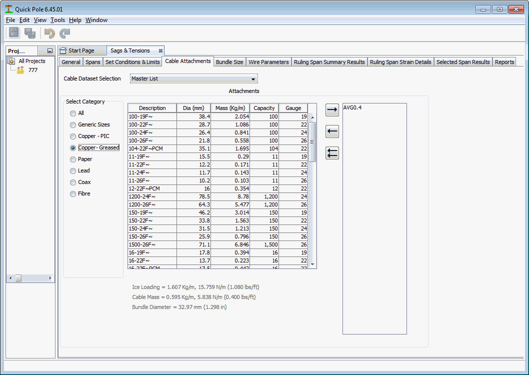
This tab defaults to show the “Master” list of all communication cables as it includes most cables you will ever need. By choosing a different Organizational Dataset, other cables may be available. When first displayed, the category is set to “All” so that you can see all communication cables. Several different category selections are available so that you can filter the list for the type you are trying to find. The heading in the list that is displayed allows you to sort the list by left-clicking once or twice by the column desired.
When you find the cable you want in the centre table listing, double-click the corresponding row to place it in the attached cable listing on the right-hand side. Alternatively you can click the row once to select the cable and use the Right Arrow button to copy it to the list. The cable attached listing works in a similar way in that you can select the item and press the Left Arrow button to remove it from the list. The Double Left Arrow button removes all items from the attached cable list. As cables are added or removed, you are presented with calculated results for Bundle Diameter, Cable Mass and Ice Loading in Imperial and Metric units. These are located under the table in the center of the Dialog.
Bundle Size
This Window Tab shows the resultant physical bundle of the wire with all selected cables attached. If no cables are attached, only the wire or self supporting cable will be shown.
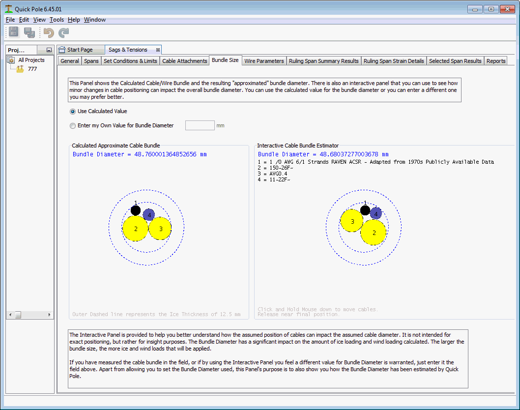
The inner dashed circle represents the approximation of the cable/wire bundle size. The Outer dashed circle represents the extent that the Storm Ice will build up on the estimated bundle size. The resultant Outer circle is the estimated size that Wind Pressure will push against. The area between the two dashed circles represents the amount of frozen precipitation that is estimated to attach to the bundle. It is recognized that the ice amount will never form into a perfect circle and leave air gaps (voids) beneath it. However this estimation is considered valid by many assuming that this volume of ice will form closely around the actual bundle.
If you have reason to believe that the bundle size is different than the size calculated, select the Radiobutton to enter your own value and enter it in the field provided.
The bundle diagram on the right is interactive and allows you to use the mouse and drag cables to a different location within the bundle. As the cables move within the bundle, the overall bundle size will be calculated and will likely be close in value to the automated version on the left. Use this interactive model to determine if there is a better estimate of bundle size than the automated one.
Wire Parameters
This Window Tab shows details about the Wire being used. It shows all of the regular data you would expect, plus the non-linear material parameters for up to two dissimilar materials used in its construction.
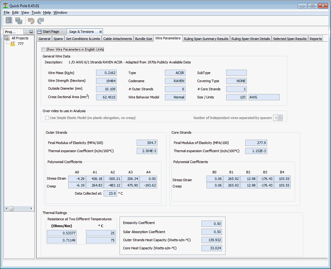
For details on what each field value means, refer to the Data Manager.
Ruling Span Summary Results
This Window Tab shows the calculated Sag & Tension Results for the Ruling Span. This tab is meant to provide summary results, focused on tensions and sags.
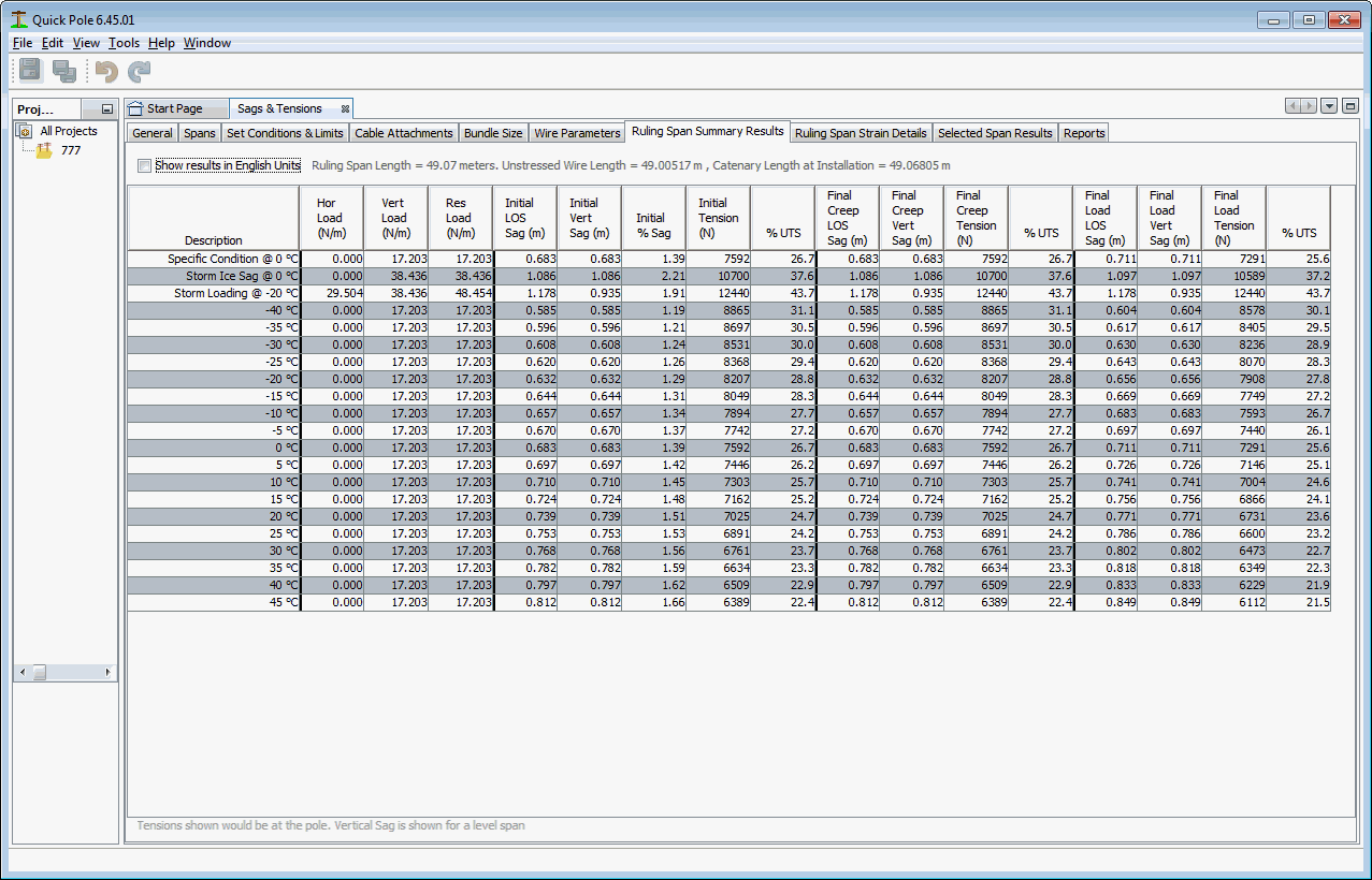
There will be a separate row in the table for each load condition requested, plus non-loaded over the temperature range enabled.
Field Descriptions
Hor. Load
Horizontal Lateral Load (such as from wind), expressed as force/unit length of wire
Vert Load
Vertical Load, such as the weight of the wire and ice.
Res Load
Resultant of the Horizontal and Vertical Loads. Both loads are combined
Field Descriptions
(Repeated for Initial, Final Creep and Final Load Categories)
LOS Sag
Line of Sight Sag, based on Tensions
Vert Sag
Vertical component of Sag, based on Tensions
% Sag
Line of Sag under Conditions expressed as a percentage of the Span Length
Tension
Tension of the wire under Conditions and measured at the upper support.
% UTS
Tension expressed as a percentage of the Ultimate Tensile Strength rating.
Ruling Span Strain Results
This Window Tab shows the calculated Sag & Tension Results for the Ruling Span. This tab is meant to provide detailed results, focused on component material tensions and strains.
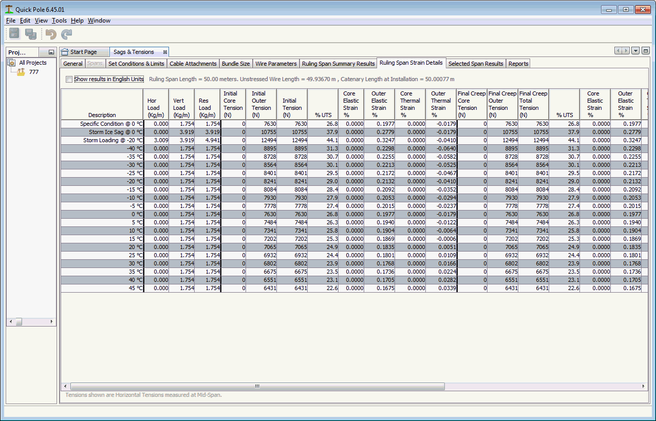
Field Descriptions - Common
Hor. Load
Horizontal Lateral Load (such as from wind), expressed as force/unit length of wire
Vert Load
Vertical Load, such as the weight of the wire and ice.
Res Load
Resultant of the Horizontal and Vertical Loads. Both loads are combined
Field Descriptions
(Repeated for Initial, Final Creep and Final Load Categories)
Core Tension
Assuming a wire with two separate materials, this represents the tension in the core.
Outer Tension
Tension in the outer material (if there are two materials in the wire) or for the whole wire if just one.
Tension
Total of the Inner and Outer Tension values.
% UTS
Total Tension expressed as a percentage of the Ultimate Tensile Strength
Core Elastic Strain
Elastic Strain (stretch per unit length) in the Core of the wire, if there are two different materials in the wire.
Outer Elastic Strain
Elastic Strain (stretch per unit length) in the Outer area of the wire, or the whole wire if there is only one material in the wire.
Core Thermal Strain
Thermal Strain (stretch per unit length) in the Core of the wire, if there are two different materials in the wire. This strain is related only to the temperature difference that this section of the wire undergoes.
Outer Thermal Strain
Thermal Strain (stretch per unit length) in the Outer section of the wire, or the whole wire if there is only one material in the wire.. This strain is related only to the temperature difference that this section of the wire undergoes.
Selected Span Results
This Window Tab shows the calculated Sag & Tension Results for the Selected Span. The specific Selected Span can be selected in the Spans Tab, or defaults to the single span and elevation difference entered on the first tab. This tab is meant to provide detailed results, focused on tensions and sags. Also highlighted are the upper and lower support tensions along with the horizontal tension.
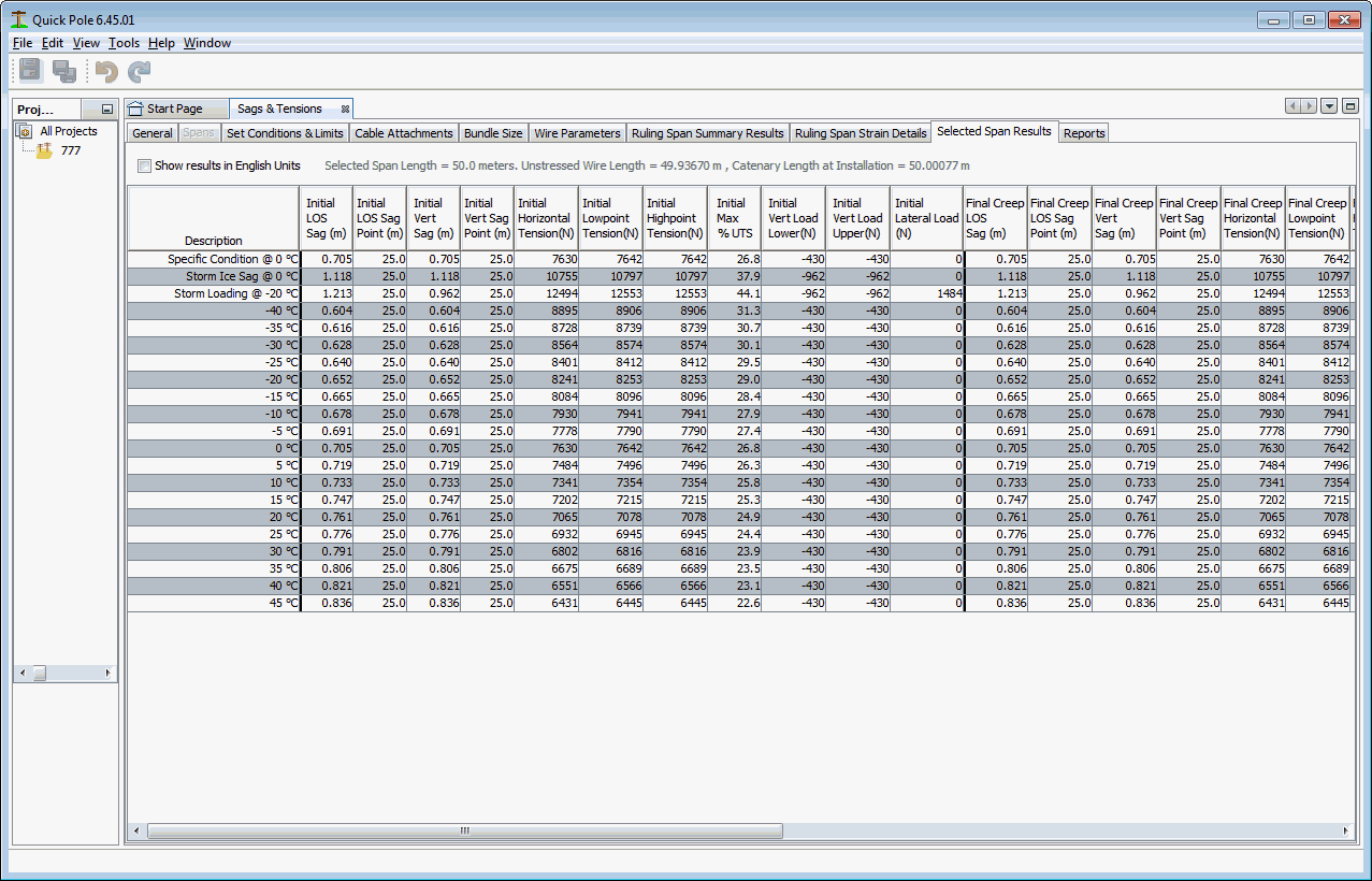
Field Descriptions
(Repeated for Initial, Final Creep and Final Load Categories)
LOS Sag
Line of Sight Sag. This is the distance between an imaginary line drawn between the attachment points on each end (which could be at different elevations); called Line of Sight and the sag of the wire/cable.
LOS Sag Point
The distance from the lower support structure to the point of the greatest Line of Sight Sag
Vert Sag
This is the amount of vertical sag below the lowest of either attachment points. If lateral (wind) loads are present or if there is a difference in elevations of the attachment points, this value will be different than the Line of Sight Sag. If the amount of elevation difference between the attachment points is too great, there will be no "real" point where the wire/cable sags below the two attachment points. In these cases, a value is provided that represents what the sag would be if the sag profile was projected to its maximum vertical sag point. This special situation is indicated if the Vertical Sag Point is a negative value.
Vert Sag Point
This is the point where the maximum amount of vertical sag occurs in the wire/cable. This value can be different than the Line of Sight Sag Point if lateral (wind) loads are present or if there is a difference in elevations of the attachment points. This point is always measured from the lowest attachment point.
Horizontal Tension
This is the amount of tension that would be measured at the Vertical Sag Point. This is the guy-able tension component of the wire/cables tension.
Lowpoint Tension
This is the amount of tension that would be measured at the lowest supporting structure/pole.
Highpoint Tension
This is the amount of tension that would be measured at the highest supporting structure/pole.
Max %UTS
This is the maximum tension (Highpoint tension) expressed as a percentage of the wire/cables Ultimate Tensile Strength.
Vert Load Lower
This is the vertical force that will exist on the lowest attachment support. It includes the weight of the wire/cable and any frozen precipitation present.
Vert Load Upper
This is the vertical force that will exist on the highest attachment support. It includes the weight of the wire/cable and any frozen precipitation present.
Lateral Load
This is the lateral, or 90 degrees horizontally, force that is being applied to this wire/cable; usually from wind. It represents the total load for the span; of which the standard practice is to apply one-half of this amount to the supporting structures for Structural Analysis purposes.
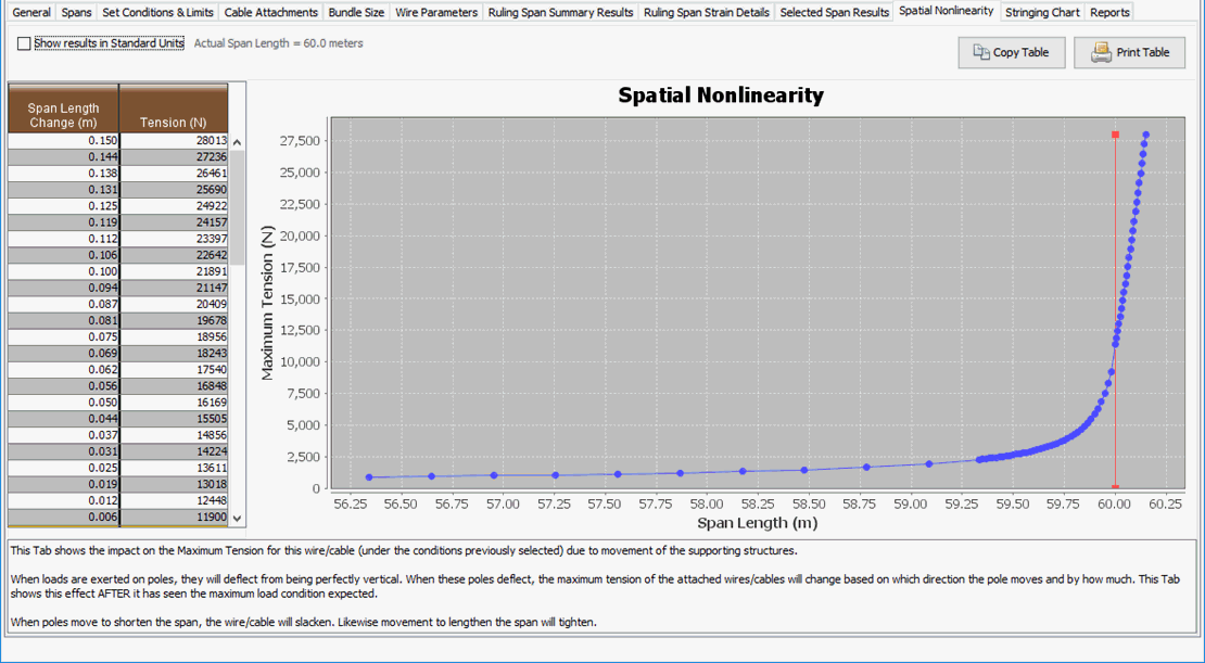
Spatial Nonlinearity
This tab shows how the wire's tension under Maximum Tension conditions will change if the structures that are supporting it deflect under load. These results are utilized in all Attachment Nonlinearity calculations at the project level.
Stringing Chart
This tab assists Utilities in the documentation of their Sags and Tension Standards.
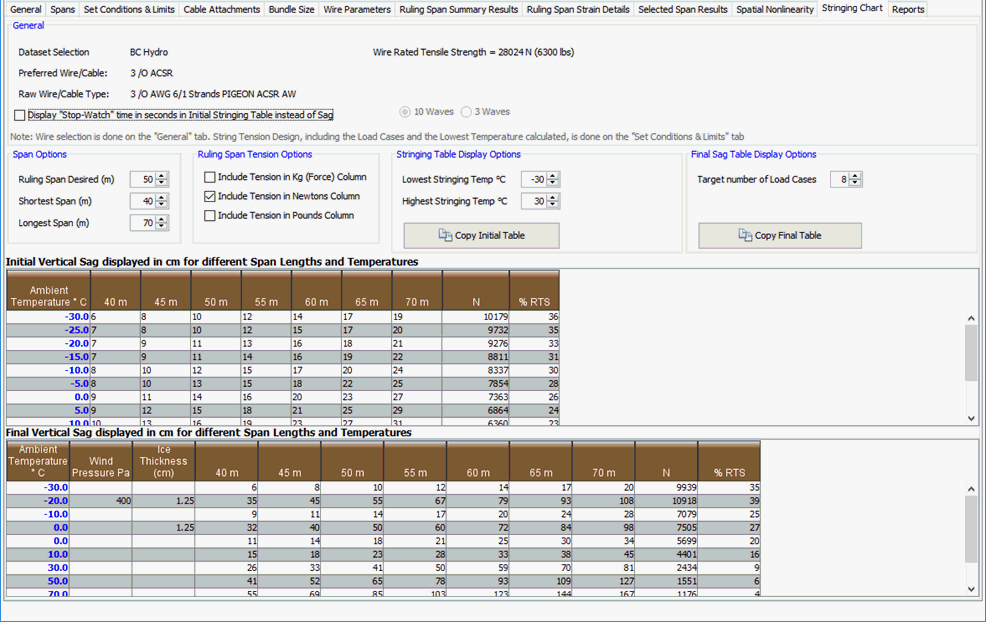
Based on the complete design of this wire's conditions and requirements specified in other tabs, this tab allows you to create a standard Stringing Sags/Tension Chart as well as a Final Tension/Sag Chart. There are multiple options on this tab to help customize the documentation the way you require. When you have the required number of span columns and load cases, use the two "Copy xx Table" buttons to copy the tables for later pasting into a Word, Excel, AutoCad or other document. Since most Utilities have their own documentation templates and standards, this was seen as the most effective means of providing the information. The information is available on your computer's clipboard in both plain text and formatted text formats. In programs such as Excel you can choose the format off the clipboard that you desire before Pasting into your document.
Reports
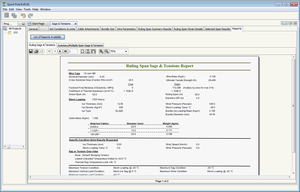
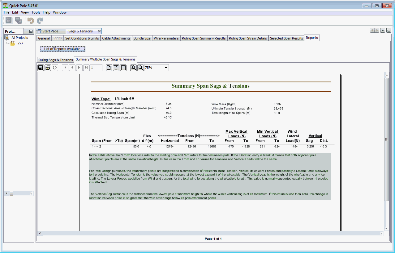
There are presently two different reports provided to summarize the results generated. The first report focusses on the Ruling Span results and the second report focusses on viewing results across various spans at each supporting structure.
Ruling Span Report
Summary / Multiple Span Report
Created with the Personal Edition of HelpNDoc: Easy to use tool to create HTML Help files and Help web sites